We got a question from [DC Darsen], who apparently has a broken electronic organ from the mid-70s that needs a new top-octave generator. A top-octave generator is essentially an IC with twelve or thirteen logic counters or dividers on-board that produces an octave’s worth of notes for the cheesy organ in question, and then a string of divide-by-two logic counters divide these down to cover the rest of the keyboard. With the sound board making every pitch all the time, the keyboard is just a simple set of switches that let the sound through or not. Easy-peasy, as long as you have a working TOG.
I bravely, and/or naïvely, said that I could whip one up on an AVR-based Arduino, tried, and failed. The timing requirements were just too tight for the obvious approach, so I turned it over to the Hackaday community because I had this nagging feeling that surely someone could rise to the challenge.
The community delivered! Or, particularly, [Ag Primatic]. With a clever approach to the problem, some assembly language programming, and an optional Arduino crystalectomy, [AP]’s solution is rock-solid and glitch-free, and you could build one right now if you wanted to. We expect a proliferation of cheesy synth sounds will result. This is some tight code. Hat tip!
Squeezing Cycles Out of a Microcontroller
Let’s take a look at [AP]’s code. The approach that [AP] used is tremendously useful whenever you have a microcontroller that has to do many things at once, on a rigid schedule, and there’s not enough CPU time between the smallest time increments to do much. Maybe you’d like to control twelve servo motors with no glitching? Or drive many LEDs with binary code modulation instead of primitive pulse-width modulation? Then you’re going to want to read on.
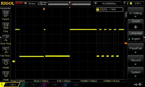
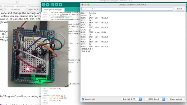
There are two additional tricks that [AP] uses: one to fake cycles with a non-integer number of counts, and one to make the AVR’s ISR timing absolutely jitter-free. Finally, [Ag] ended up writing everything in AVR assembly language to make the timing work out, but was nice enough to also include a C listing. So if you’d like to get your feet wet with assembly, this is a good start.
In short, if you’re doing anything with hard timing requirements on limited microcontroller resources, especially an AVR, read on!
Continue reading “Ask Hackaday Answered: The Tale Of The Top-Octave Generator”