A 6502 Computer, With Acres Of Breadboard And Dozens Of Chips

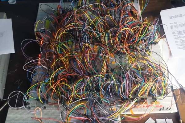
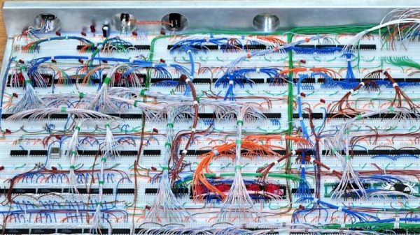
Imagine you’re time-warped back to 1979 and tasked with constructing a personal computer. Could you do it? [RadicalBrad] thinks he can, and his 6502-based “Super VIC” build looks like it’s off to a great retrocomputing start.

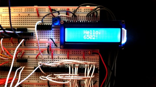
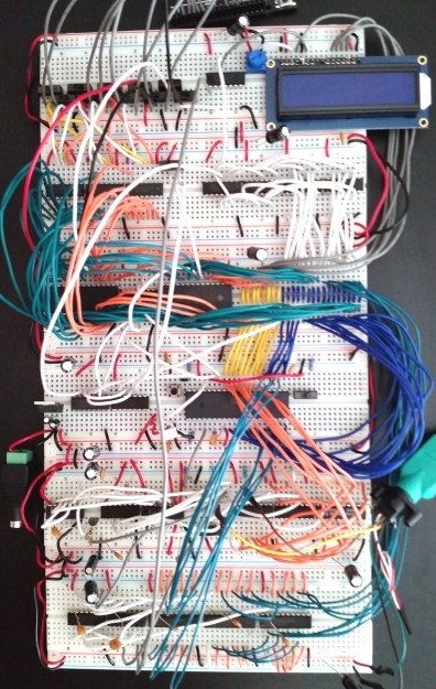
Most emulations of old hardware these days go the FPGA route, and while we respect those projects immensely, there’s something to be said for applying a highly artificial constraint at the outset of a project. [RadicalBrad] chose to design like it’s 1979, and limited his ode to the machines of his youth to the 6502 CPU and logic and RAM chips available before 1980. The computer will support NTSC video output and 4-channels of 8-bit sound. No circuit boards will be used – everything is to be assembled on solderless breadboards. So far he has 48 (!) of them ganged together, which sounds like an enormous amount of space to work with, but he still found things crowded enough that some of the DIP bodies were trimmed a bit to fit more closely on the breadboards. The SRAM posed a problem, though, in that the 512K chips he wanted were not available in DIPs. To stay faithful to the constraints, he soldered the SOJ-packaged RAM chips into 40-PIN DIP headers – all 25 chips! We can’t recall a PC of the era sporting 12 megabytes of RAM, but no matter – it’s too cool not to love.

[RadicalBrad] has his work cut out for him, and this could take years to finish. We’re keen to follow his progress and can’t wait till it boots for the first time. Until it does, we’ll just gaze upon such discrete computing wonders as this almost-as-simple-as-possible computer, or even this delightfully noisy adder for a relay computer.

Making Your Breadboard Projects A Little More Permanent

Many a budding electronics maker got their start not with a soldering iron, but with the humble breadboard. With its push connections, the breadboard enables electronics experimentation without requiring the specialised skill of soldering or any dangerous hot tools. What it lacks is a certain robustness that can make all but the simplest projects rather difficult to execute. [Runtime Micro] have shared a few tips on making things just a little more robust, however.

Applied correctly, these techniques have the added bonus of making a project neat, tidy, and easy to troubleshoot.

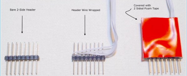
The fundamental principle behind this process is replacing point-to-point jumper wires with custom cables, made using 0.1″ pitch headers and wire-wrapping techniques. Other techniques include pinning down components with Blu-tack, and selecting components with the appropriate wire diameter to avoid them falling out of the breadboard’s spring clip contacts. There are also useful tips on using foam tape for appropriate strain relief.

While breadboards aren’t really suitable for projects dealing with high frequencies and can rapidly become unmanageable, these basic techniques should improve a project’s chance of success. These simple ways of improving connection quality and reducing the likelihood of things falling apart are likely to reduce frustration immensely.

However, once a maker has a taste for corralling electrons to do their bidding, soldering should be the first lesson on the agenda.

[Thanks to stockvu for the tip!]

The Solution To Oversized Dev Boards: A Literal Hack

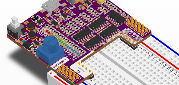
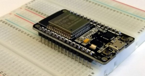
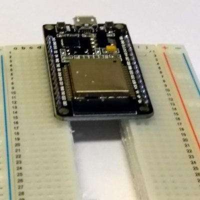
Oh, there was a time when you could prototype just about everything on a breadboard. The CPU in your computer came in a DIP package, and there were no BGA packages. to be found anywhere. In the forty years since then, chips have gotten smaller, packages have gotten more cramped, and you can barely hand-solder the coolest chips anymore. No worries — companies are still spitting out dev boards with 0.1″ headers, but there’s a problem: they don’t fit on a solderless breadboard. They’re too wide. Our world is falling apart.

[Luc] had a problem when he was playing with a few NodeMCU dev boards. These are too wide for a breadboard. [Luc] came up with not just one solution, but two. This is how you prototype with dev boards that are too large.

The solution came to [Luc] when he realized the center of every breadboard has no electrical connections, and was simply held together by a little piece of plastic. Yes, he took a hacksaw to the breadboard. This is technically a hack.

With two halves of a solderless breadboard torn asunder, [Luc] had an easy way to prototype with dev boards that are just too wide. But there is a simpler solution [Luc] realized after he destroyed a breadboard: those ubiquitous solderless breadboards have detachable power rails. If you simply take one of those power rails off, you have an easy way to use two breadboards across a module that’s too wide for one solderless breadboard.

Is this a hack? Oh, absolutely. [Luc] used a hacksaw. It’s also a nice reminder of a common trick that the noobies might not know. Thanks for that, [Luc].

A 6502 With A Custom Language

The 6502 has a long history with hackers. The Apple computer (the one with no keyboard or even case) had a 6502. So did the Kim-1. [Dolo’s] version is a bit more refined, though. He started it a few years ago in response to one of our contests, but he’s been making improvements to it ever since. In particular, the custom programming language, Dflat, has many improvements lately, including true functions and high-resolution drawing.

The hardware has a CPU running at over 2.5 MHz, 44K of RAM, 16K of PROM, and 16K of video RAM. There’s plenty of I/O, including a keyboard, sound, and joysticks. An SD card provides mass storage and it all goes in a hacked BBC Micro case. You can see an overview video, below.

Continue reading “A 6502 With A Custom Language”

Home Made 8-Bit CPU Is A Wiry Blinky Build

It might look like a random pile of wires to some, but it is far from random: [Paulo Constantino] built this 8-bit CPU himself from scratch. He built his remarkable creation using wires and 74HC shift register chips, plus a selection of LEDs to show the various registers.

Running at a maximum of 5MHz, it has an 8-bit data and address bus, although the latter can be expanded to 16 bits. It’s not mining Bitcoin (yet), but it can do things like play the Mario theme. His latest addition is the addition of the ability to write data out to flash memory, and he is looking to add a keyboard to make programming easier.

At the moment, he has to program the CPU by setting DIP jumpers. It’s an impressive, if somewhat frightening build that [Paulo] says took him a couple of days to design and a week or so to build. We’ve seen a few breadboard CPU builds, (some of which were tidier) and builds with similar shift register chips, but this one scores big in the blinky light and mad genius stakes.

Thanks to [AnalogMind] for the tip!

Continue reading “Home Made 8-Bit CPU Is A Wiry Blinky Build”

Making An Arduino Shield PCB With Fritzing

[Allan Schwartz] decided to document his experience using Fritzing to design, fabricate, and test a custom Arduino shield PCB, and his step-by-step documentation makes the workflow very clear. Anyone who is curious or has been looking for an opportunity to get started will find [Allan]’s process useful to follow. The PCB in question has two shift registers, eight LEDs, eight buttons, and fits onto an Arduino; it’s just complex enough to demonstrate useful design features and methods while remaining accessible.

[Allan] starts with a basic breadboard design, draws a schematic, prototypes the circuit, then designs the PCB and orders it online, followed by assembly and testing. [Allan] had previously taught himself to use Eagle and etched his own PCBs via the toner transfer method, but decided to use Fritzing instead this time around and found it helpful and easy to use.

About a year ago we saw Fritzing put through its paces for PCB design, and at the time found that it didn’t impress much from an engineering perspective. Regardless, as a hobbyist [Allan] found real value in using Fritzing for his project from beginning to end; he documented both the process and his observations in order to help others, and that’s wonderful.

No-Solder Breadboarding For SMD LEDs

Breadboarding is a great way to get started with electronics, and with the wide availability of those little wire jumpers, it’s never been easier – until you hit roadblocks due to poor connections and parasitic capacitance futzing with your signals. However, in today’s current climate, the latest and greatest modules are too often available only in SMD packages, and while breakout boards can help, it’s probably overcomplicating things a bit when it comes to SMD LEDs. It’s all good, though – [Simon Merrett] has a workaround, as part of his Yapolamp project.

[Simon] first took a flat strip of steel, and placed two neodymium magnets on top. The assembly was then wrapped in electrical tape for insulation, and two contacts were created with copper tape. The LEDs were then placed across the two contacts and wires were attached to join them to the breadboard. The 5630 LEDs [Simon] must contain some sort of ferrous material, because they were attracted to the magnets and sat neatly in place.

It’s a neat hack that would be particularly useful if you needed to quickly swap out LEDs, and saves them from damage by soldering. Meanwhile, check out this SMD LED matrix from 2009.