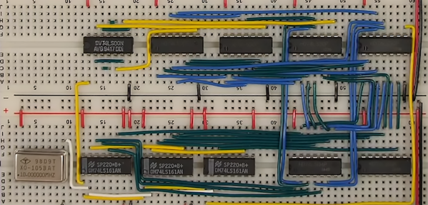
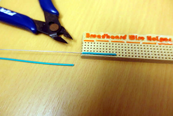
CPU Made From 74HC Chips Is A Glorious Mess

Did you ever start a project that you felt gained a life of its own? This project by [Paulo Constantino] is an entire CPU named dreamcatcher on breadboards, and is a beautiful jungle of digital. On top of that, it works to connect to an analog VGA display. How cool is that!

Designing an ALU and then a CPU is a typical exercise for students of digital design and is done using VerilogHDL or VHDL. It involves creating an ALU that can add, subtract etc while a control unit manages data moves and the like. There is also a memory fetch and instruction decode made up of de-mulitiplexers and a bunch of flip-flops that make up registers and flags. They are as complex as they sound if not more.

[Paulo Constantino] went ahead and designed the whole thing in Eagle as a schematic using 74HC logic chips. To build it though instead of a PCB he used breadboards. Everything from bus decoders to controlling an external VGA display is done using jumper wires. We did cover a video on the project a while back, but this update adds a video card interface to the build.

The CPU updates the display buffer on the VGA card, and in the video below shows the slow and steady update. The fact that the jungle of wires can drive a display is awesome. He has since started working on a 16-bit version of the processor and we’d love to see someone take it up a notch.

For those more accustomed to the PCB, the Z80 membership card project is a great build for 8-bit computer fans.

Thanks to [analog engineer] for the tip.

Continue reading “CPU Made From 74HC Chips Is A Glorious Mess”

A Breadboard Power Supply That’s More Universal Than Most

A favorite project of ours is the humble breadboard power supply. Yes, you can still prototype on breadboards, no, you don’t need an entire bench power supply to prototype on one, and every breadboard made in the last forty years has had the same pattern of holes. There’s plenty of opportunity to improve the breadboard power supply.

One of the best ones we’ve seen yet comes from [John Loeffler]. It’s a simple, constant voltage power supply that’s variable from 0.6 V all the way up to 12 V. It’s powered through a micro USB port, and you get 3.3 V and 5 V rails automagically. There’s even voltage indication.

The mechanical design of this power supply is simple enough, with pins that plug into the detachable power rails on either side of the breadboard. Where it gets interesting is the voltage indication. There’s a resistor ladder and a series of LEDs to indicate the voltage on the variable side of this power supply. Add in some modern switched mode power supply based on the MIC5225 series of chips (a popular regulator that’s very nice for the price) and you have a completely functional power supply hanging off a breadboard.

While it’s not a really nice rack mounted bench power supply that weighs a lot, or even one of the cheapo bench supplies, this does fulfill a need. Sometimes you just need a simple power supply for a breadboard, and this is one of the best ones we’ve seen yet.

A Nearly Practical 6502 Breadboard Computer

Over the years we’ve seen a number of homebrew 6502 computers assembled with little more than a breadboard, a sack full of jumper wires, and an otherworldly patience that would make a Buddhist Monk jealous. Anyone who takes the time to assemble a fully functional computer on a half-dozen breadboards lined up on their workbench will always be a superstar in our book.

While we’re still too lazy to attempt one of these builds ourselves, we have to admit that the Vectron 64 by [Nick Bild] looks dangerously close to something you might be able to pull off within a reasonable amount of time. It’s still an incredible amount of work, but compared to some of the other projects we’ve seen, this one manages to keep the part count relatively low thanks to the use of a simple 16×2 LCD for output and user input provided by a PS/2 keyboard. You won’t be playing Prince of Persia on it, but at least you might be able to finish it in a weekend.

The computer is clocked at 1 MHz, and features 32KB RAM
along with 32KB EEPROM. That should be enough for anyone. [Nick] also points out he tried to use era-appropriate 7400 series ICs wherever possible, so no worries about historical revisionism here. If you’re looking for a design that somebody could have potentially knocked together back in the 1970s, this one would get you fairly close.

The astute reader might notice there’s no removable media in this build, and may be wondering how one loads programs. For that, [Nick] allowed himself a bit of modern convenience and came up with a scheme that allows an Arduino (or similar microcontroller) to connect up to the computer’s 28C256-15 EEPROM. With a Python script running on your “real” computer, you can write a new ROM image directly to the chip. He’s included the source code for a simple program which will write whatever you type on the keyboard out on the LCD, which should give you a good framework for writing additional software.

If you’re looking for a bigger challenge, don’t worry. We’ve covered 6502 breadboard computers that will make your eyes water. Incidentally, this isn’t the first time we’ve seen a similar LCD used for one of these computers, so looks like there’s no shame in sneaking in modern parts where it makes sense.

Hexagons – The Crazy New Breadboard

A breadboard is a great prototyping tool for verifying the sanity of a circuit design before taking the painstaking effort of soldering it all together permanently. After all, a mistake in this stage can cost a lot of time and possibly material, so it’s important to get it right. [daverowntree] wasn’t fully satisfied with the standard breadboard layout though, with fixed rows and columns. While this might work for most applications, he tried out a new type of prototyping board based on hexagons instead.

The design philosophy here revolves around tessellations, a tiling method for connecting the various components on this unique breadboard rather than using simple rows. The hexagons are tessellated across the board, allowing for some unique combinations that might make it slightly more complicated, but can have some benefits for other types of circuits such as anything involving the use of a three-wire device like a transistor.

The post is definitely worth a read, as [daverowntree] goes through several examples of this method of prototyping where the advantages are shown, like a voltage follower circuit and some other circuits involving transistor biasing. If you’re OK with the general design of breadboards, though, and just wished you didn’t have to do anything after the prototyping stage, we’ve got some help for you there as well.

A 6502 Computer, With Acres Of Breadboard And Dozens Of Chips

Imagine you’re time-warped back to 1979 and tasked with constructing a personal computer. Could you do it? [RadicalBrad] thinks he can, and his 6502-based “Super VIC” build looks like it’s off to a great retrocomputing start.

Most emulations of old hardware these days go the FPGA route, and while we respect those projects immensely, there’s something to be said for applying a highly artificial constraint at the outset of a project. [RadicalBrad] chose to design like it’s 1979, and limited his ode to the machines of his youth to the 6502 CPU and logic and RAM chips available before 1980. The computer will support NTSC video output and 4-channels of 8-bit sound. No circuit boards will be used – everything is to be assembled on solderless breadboards. So far he has 48 (!) of them ganged together, which sounds like an enormous amount of space to work with, but he still found things crowded enough that some of the DIP bodies were trimmed a bit to fit more closely on the breadboards. The SRAM posed a problem, though, in that the 512K chips he wanted were not available in DIPs. To stay faithful to the constraints, he soldered the SOJ-packaged RAM chips into 40-PIN DIP headers – all 25 chips! We can’t recall a PC of the era sporting 12 megabytes of RAM, but no matter – it’s too cool not to love.

[RadicalBrad] has his work cut out for him, and this could take years to finish. We’re keen to follow his progress and can’t wait till it boots for the first time. Until it does, we’ll just gaze upon such discrete computing wonders as this almost-as-simple-as-possible computer, or even this delightfully noisy adder for a relay computer.

Making Your Breadboard Projects A Little More Permanent

Many a budding electronics maker got their start not with a soldering iron, but with the humble breadboard. With its push connections, the breadboard enables electronics experimentation without requiring the specialised skill of soldering or any dangerous hot tools. What it lacks is a certain robustness that can make all but the simplest projects rather difficult to execute. [Runtime Micro] have shared a few tips on making things just a little more robust, however.

Applied correctly, these techniques have the added bonus of making a project neat, tidy, and easy to troubleshoot.

The fundamental principle behind this process is replacing point-to-point jumper wires with custom cables, made using 0.1″ pitch headers and wire-wrapping techniques. Other techniques include pinning down components with Blu-tack, and selecting components with the appropriate wire diameter to avoid them falling out of the breadboard’s spring clip contacts. There are also useful tips on using foam tape for appropriate strain relief.

While breadboards aren’t really suitable for projects dealing with high frequencies and can rapidly become unmanageable, these basic techniques should improve a project’s chance of success. These simple ways of improving connection quality and reducing the likelihood of things falling apart are likely to reduce frustration immensely.

However, once a maker has a taste for corralling electrons to do their bidding, soldering should be the first lesson on the agenda.

[Thanks to stockvu for the tip!]

The Solution To Oversized Dev Boards: A Literal Hack

Oh, there was a time when you could prototype just about everything on a breadboard. The CPU in your computer came in a DIP package, and there were no BGA packages. to be found anywhere. In the forty years since then, chips have gotten smaller, packages have gotten more cramped, and you can barely hand-solder the coolest chips anymore. No worries — companies are still spitting out dev boards with 0.1″ headers, but there’s a problem: they don’t fit on a solderless breadboard. They’re too wide. Our world is falling apart.

[Luc] had a problem when he was playing with a few NodeMCU dev boards. These are too wide for a breadboard. [Luc] came up with not just one solution, but two. This is how you prototype with dev boards that are too large.

The solution came to [Luc] when he realized the center of every breadboard has no electrical connections, and was simply held together by a little piece of plastic. Yes, he took a hacksaw to the breadboard. This is technically a hack.

With two halves of a solderless breadboard torn asunder, [Luc] had an easy way to prototype with dev boards that are just too wide. But there is a simpler solution [Luc] realized after he destroyed a breadboard: those ubiquitous solderless breadboards have detachable power rails. If you simply take one of those power rails off, you have an easy way to use two breadboards across a module that’s too wide for one solderless breadboard.

Is this a hack? Oh, absolutely. [Luc] used a hacksaw. It’s also a nice reminder of a common trick that the noobies might not know. Thanks for that, [Luc].