Simplify 3D Printer Wiring With CAN Bus

[mark] had an interesting idea when looking at all the wiring of a typical 3D printer; Use CAN Bus. There are a lot of wires going to the extruder assembly, and with most designs this thing is flying around at quite some speed. You’ve got connections for powering the heater, fan power, four wires for the extruder motor, thermistor sensor wires. You get the idea. Lots of wires. Worse, they’re all moving around with the axis, and if failures occur at either end due to poor strain relief, or the conductors themselves break, then all manner of interesting failures can occur. If the hot end thermistor connection goes open circuit, usually no damage occurs but the temperature control goes out the window and your print will fail.

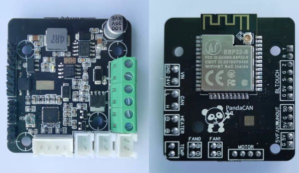
Now if you push the electronics needed to drive and control the extruder, directly onto the moving body itself, and hook-up to the main printer electronics with CAN Bus, you can do the whole moving interconnect thing with a measly four wires. Yes, you need another PCB assembly, so it adds cost, but it does also simply the electronics at the control end, so some savings can be made. [mark] has used CAN Bus due its availability with modern microcontrollers and also its designed-in robustness, thanks to its automotive and industrial heritage. When you think about it, this is a rather obvious thing to do, and we’re not sure why we’ve not see it much before.

If you want to dig into the detail, the project GitHub has the schematics and code ready to go.


Continue reading “Simplify 3D Printer Wiring With CAN Bus”

Flamethrower weedkiller mounted on a robot arm riding a tank tracked base

Don’t Sleep On The Lawn, There’s An AI-Powered, Flamethrower-Wielding Robot About

You know how it goes, you’re just hanging out in the yard, there aren’t enough hours in the day, and weeding the lawn is just such a drag. Then an idea just pops into your head. How about we attach a gas powered flamethrower to a robot arm, drive it around on a tank-tracked robotic base, and have it operate autonomously with an AI brain? Yes, that sounds like a good idea. Let’s do that. And so, [Dave Niewinski] did exactly that with his Ultimate Weed Killing Robot.

And you thought the robot overlords might take a more subtle approach and take over the world one coffee machine at a time? No, straight for the fully-autonomous flamethrower it is then.

This build uses a Kinova Robots Gen 3 six-axis arm, mounted to an Agile-X Robotics Bunker base. Control is via a Connect Tech Rudi-NX box which contains an Nvidia Jetson Xavier NX Edge AI computing engine. Wow that was a mouthful!

Connectivity from the controller to the base is via CAN bus, but, sadly no mention of how the robot arm controller is hooked up. At least this particular model sports an effector mount camera system, which can feed straight into the Jetson, simplifying the build somewhat.

To start the software side of things, [Dave] took a video using his mobile phone while walking his lawn. Next he used RoboFlow to highlight image stills containing weeds, which were in turn used to help train a vision AI system. The actual AI training was written in Python using Google Collaboratory, which is itself based on the awesome Jupyter Notebook (see also Jupyter Lab on the main site. If you haven’t tried that yet, and if you do any data science at all, you’ll kick yourself for not doing so!) Collaboratory would not be all that useful for this by itself, except that it gives you direct, free GPU access, via the cloud, so you can use it for AI workloads without needing fancy (and currently hard to get) GPU hardware on your desk.

Details of the hardware may be a little sparse, but at least the software required can be found on the WeedBot GitHub. It’s not like most of us will have this exact hardware lying around anyway. For a more complete description of this terrifying contraption, checkout the video after the break.

Continue reading “Don’t Sleep On The Lawn, There’s An AI-Powered, Flamethrower-Wielding Robot About”

Custom Instrument Cluster For Aging Car

All of the technological improvements to vehicles over the past few decades have led to cars and trucks that would seem borderline magical to anyone driving something like a Ford Pinto in the 1970s. Not only are cars much safer due to things like crumple zones, anti-lock brakes, air bags, and compulsory seat belt use, but there’s a wide array of sensors, user interfaces, and computers that also improve the driving experience. At least, until it starts wearing out. The electronic technology in our modern cars can be tricky to replace, but [Aravind] at least was able to replace part of the instrument cluster on his aging (yet still modern) Skoda and improve upon it in the process.

These cars have a recurring problem with the central part of the cluster that includes an LCD display. If replacement parts can even be found, they tend to cost a significant fraction of the value of the car, making them uneconomical for most. [Aravind] found that a 3.5″ color LCD that was already available fit perfectly in the space once the old screen was removed, so from there the next steps were to interface it to the car. These have a CAN bus separated from the main control CAN bus, and the port was easily accessible, so an Arduino with a RTC was obtained to handle the heavy lifting of interfacing with it.

Now, [Aravind] has a new LCD screen in the console that’s fully programmable and potentially longer-lasting than the factory LCD was. There’s also full documentation of the process on the project page as well, for anyone else with a Volkswagen-adjacent car from this era. Either way, it’s a much more economical approach to replacing the module than shelling out the enormous cost of OEM replacement parts. Of course, CAN bus hacks like these are often gateway projects to doing more involved CAN bus projects like turning an entire vehicle into a video game controller.

Continue reading “Custom Instrument Cluster For Aging Car”

CAN Bus Wireless Hacking / Dev Board

[Voltlog] has been hacking away at the CAN bus console of his VW Golf for quite some time now. Presumably, for his projects, the available CAN bus interface boards are lacking in some ways, either technically and/or price. So [Voltlog] designed his own wireless CAN bus hacking and development module called the ESP32 CanLite (see the video below the break). The board was tailored to meet the needs of his project and he claims it is not a universal tool. Nevertheless we think many folks will find the features he selected for this module will be a good fit for their projects as well.

In his introduction of the design, he walks through the various design decisions he faced. As the project name suggests, he’s using the ESP32 as the main controller due to it’s wireless radios and built-in CAN controller. The board is powered from the car’s +12V power, so it uses a wide input range ( 4 to 40 V ) switching regulator. One feature he added was the ability to switch automotive accessories using the ST VN750PC, a nifty high-side driver in an SO-8 package with integrated safety provisions.

The project is published as open source and the files can be pulled from his GitHub repository. We noticed the debug connector labeled VOLTLINK on the schematic, and found his description of this custom interface interesting. Basically, he was not satisfied with the quality and performance of the various USB-to-serial adapters on the market and decided to make his own. Could this be a common theme among [Voltlog]’s projects?

A word of warning if you want to build the ESP32 CanLite yourself. While [Voltlog] had intentionally selected parts that were common and easy to purchase when the project began, several key chips have since become nearly impossible to obtain these days due to the global parts shortage issue (it’s even out of stock on his Tindie page).

If you want to dig deeper into CAN bus hacking, check out this talk that we wrote about back in 2016. Do you have any favorite CAN bus development boards and/or tools? Let us know in the comments below.

Continue reading “CAN Bus Wireless Hacking / Dev Board”

Using CanoPy To Visualize The CAN Bus

As cars have become more sophisticated electronically, understanding the CAN bus that forms the backbone of automotive digital systems has become more and more important for hacking cars. Inexpensive microcontroller CAN interfaces have made obtaining the raw CAN bus traffic trivial, but interpreting that traffic can be pretty challenging. In order to more easily visualize CAN traffic, [TJ Bruno] has developed CanoPy, a Python tool for visualizing CAN messages in real time.

A basic PC CAN interface simply dumps the bus’s message traffic into the terminal, while more sophisticated tools organize messages by the address of their intended recipients. Both of these approaches digitally lift the hood and let you examine what your car is thinking, but the wall-of-numbers approach makes finding the patterns that hold the keys to reverse engineering difficult. Automatically plotting the data with CanoPy makes finding correlations much easier, after which the text-based tools can be used to focus in on a few specific addresses.

Continue reading “Using CanoPy To Visualize The CAN Bus”

Small Open Source Vehicle Hacking Platform

[Florian] and his engineering team at Munich-based bmc::labs has developed a clever set of prototyping boards for vehicle hacking and rapid product development, collectively called the bmc::board or bmc::mini. These stackable development boards were initially designed for in-house use. The team took a general purpose approach to the design so the boards could be used across a wide range of projects, and they should be useful to anyone in the field. [Florian] decided to release the boards to the community as open-source and certified by OSHWA (Open Source Hardware Association).

There are four boards currently defined, with several more in the works:

  • mini::base — Main microcontroller board, STM32F103-based
  • mini::out — I/O board with CAN bus, JTAG, etc.
  • mini:: grid — RF board providing GPS and GSM capability
  • mini::pit — local wireless connectivity, WiFi and Bluetooth, and 2nd CAN bus

At 54 x 42.5 mm, these boards are pretty small; a form-factor they describe as “exactly half a credit card”. We like the Wurth WR-MM family of stacking connectors they are using, and the symmetrical pinout means you can rotate the cards as needed. But at first glance, these thru-hole connectors seem to limit the stack to just two boards, although maybe they plan move to an SMT flavor of the connector in future designs permitting taller stacks.

If you’re into vehicle electronics and/or vehicle hacking, definitely take a look at these. You can check out [Florian]’s bmc::board Hackaday.io project page and the team’s GitHub repository for more details. Here’s another project by team member [Sebastian] using one of the future bmc::bike modules to eavesdrop on ECU communications, where he sensibly advises the reader “First, pull over and get off the bike. Never hack a two-wheeled vehicle while riding it!”.

No discussion of vehicle CAN bus tools should omit the work of Craig Smith, who literally wrote the book on hacking your car, and whose talk along with Hackaday’s own Eric Evenchick of CANtact fame we covered back in 2016. [Florian] has started a CrowdSupply campaign where you can see some more details of this project and a short promotional video.

Classic Triumph Gets A Modern Digital Dash

Analog gauges gave way to all manner of fancy electroluminescent and LED gauges in the ’80s, but the trend didn’t last long. It’s only in the last decade or so that LCD digital gauges have really started to take off in premium cars. [Josh] is putting a modern engine and drivetrain into his classic Triumph GT6, and realised that he’d have to scrap the classic mechanical gauge setup. After not falling in love with anything off the shelf, he decided to whip up his own solution from scratch.

The heart of the build is a Raspberry Pi 4, which interfaces with the car’s modern aftermarket ECU via CANBUS thanks to the PiCAN3 add-on board. Analog sensors, such as those for oil pressure and coolant temperature, are interfaced with a Teensy 4.0 microcontroller which has the analog to digital converters necessary to do the job. Display is via a 12.3″ super-wide LCD sourced off Aliexpress, with the graphics generated by custom PixiJS code running in Chromium under X.

The result is comparable with digital displays in many other modern automobiles, speaking to [Josh]’s abilities not just as a programmer but a graphic designer, too. As a bonus, if he gets sick of the design, it’s trivial to change the graphics without having to dig into the car’s actual hardware.

Gauge upgrades are common on restomod projects; another route taken is to convert classical mechanical gauges to electronic drive. If you’re cooking up your own sweet set of gauges in the garage, be sure to drop us a line! Video after the break.

Continue reading “Classic Triumph Gets A Modern Digital Dash”