Hackaday Prize Entry: Modular Stepper Control

Stepper motors are a great solution for accurate motion control. You’ll see them on many 3D printer designs since they can precisely move each axis. Steppers find uses in many robotics projects since they provide high torque at low speeds.

Since steppers are used commonly used for multi-axis control systems, it’s nice to be able to wire multiple motors back to a single controller. We’ve seen a few stepper control modules in the past that take care of the control details and accept commands over SPI, I2C, and UART. The AnanasStepper 2.0 is a new stepper controller that uses CAN bus for communication, and an entry into the 2017 Hackaday Prize.

A CAN bus has some benefits in this application. Multiple motors can be connected to one controller via a single bus. At low bit rates, it can work on kilometer long busses. The wiring is simple and cheap: two wires twisted together with no shielding requirements. It’s also designed to be reliable in high noise environments such as cars and trucks.

The project aims to implement an API that will allow control from many types of controllers including Arduino, Linux CNC, several 3D printer controllers, and desktop operating systems. With a few AnanasSteppers one of these controllers, you’d be all set up for moving things on multiple axes.

OBDII to Speed Pulse: Atmel ICE

Building An OBD Speed Pulse: Behold The ICE

I am a crappy software coder when it comes down to it. I didn’t pay attention when everything went object oriented and my roots were always assembly language and Real Time Operating Systems (RTOS) anyways.

So it only natural that I would reach for a true In-Circuit-Emulator (ICE) to finish of my little OBDII bus to speed pulse generator widget. ICE is a hardware device used to debug embedded systems. It communicates with the microcontroller on your board, allowing you to view what is going on by pausing execution and inspecting or changing values in the hardware registers. If you want to be great at embedded development you need to be great at using in-circuit emulation.

Not only do I get to watch my mistakes in near real time, I get to make a video about it.

Getting Data Out of a Vehicle

I’ve been working on a small board which will plug into my car and give direct access to speed reported on the Controller Area Network (CAN bus).

To back up a bit, my last video post was about my inane desire to make a small assembly that could plug into the OBDII port on my truck and create a series of pulses representing the speed of the vehicle for my GPS to function much more accurately. While there was a wire buried deep in the multiple bundles of wires connected to the vehicle’s Engine Control Module, I have decided for numerous reasons to create my own signal source.

At the heart of my project is the need to convert the OBDII port and the underlying CAN protocol to a simple variable representing the speed, and to then covert that value to a pulse stream where the frequency varied based on speed. The OBDII/CAN Protocol is handled by the STN1110 chip and converted to ASCII, and I am using an ATmega328 like found on a multitude of Arduino’ish boards for the ASCII to pulse conversion. I’m using hardware interrupts to control the signal output for rock-solid, jitter-free timing.

Walk through the process of using an In-Circuit Emulator in the video below, and join me after the break for a few more details on the process.

Continue reading “Building An OBD Speed Pulse: Behold The ICE”

Reverse-Engineering The Peugeot 207’s CAN Bus

Here’s a classic “one thing led to another” car hack. [Alexandre Blin] wanted a reversing camera for his old Peugeot 207 and went down a rabbit hole which led him to do some extreme CAN bus reverse-engineering with Arduino and iOS. Buying an expensive bezel, a cheap HDMI display, an Arduino, a CAN bus shield, an iPod touch with a ghetto serial interface cable that didn’t work out, a HM-10 BLE module, an iPad 4S, the camera itself, and about a year and a half of working on it intermittently, he finally emerged poorer by about 275€, but victorious in a job well done. A company retrofit would not only have cost him a lot more, but would have deprived him of everything that he learned along the way.

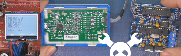
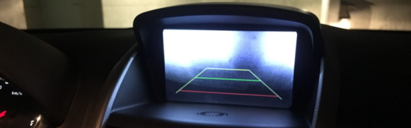
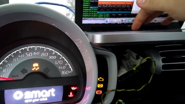
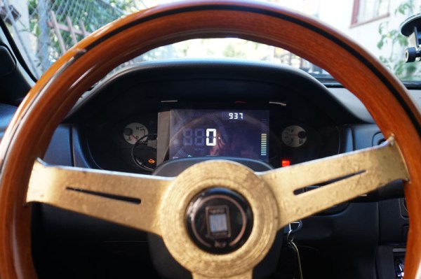
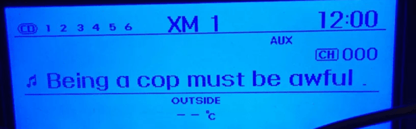
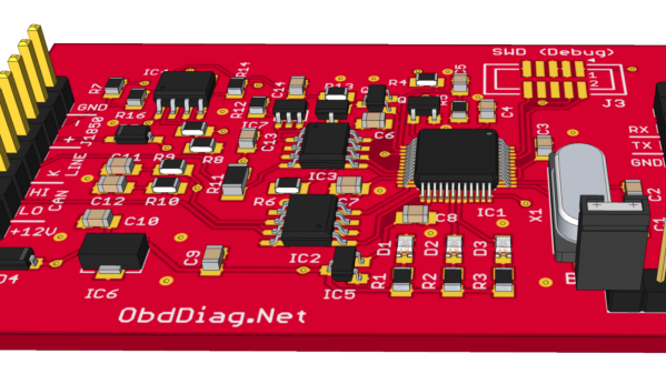
Adding the camera was the easiest part of the exercise when he found an after-market version specifically meant for his 207 model. The original non-graphical display had to make room for a new HDMI display and a fresh bezel, which cost him much more than the display. Besides displaying the camera image when reversing, the new display also needed to show all of the other entertainment system information. This couldn’t be obtained from the OBD-II port but the CAN bus looked promising, although he couldn’t find any details for his model initially. But with over 2.5 million of the 207’s on the road, it wasn’t long before [Alexandre] hit jackpot in a French University student project who used a 207 to study the CAN bus. The 207’s CAN bus system was sub-divided in to three separate buses and the “comfort” bus provided all the data he needed. To decode the CAN frames, he used an Arduino, a CAN bus shield and a python script to visualize the data, checking to see which frames changed when he performed certain functions — such as changing volume or putting the gear in reverse, for example.

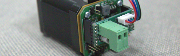
The Arduino could not drive the HDMI display directly, so he needed additional hardware to complete his hack. While a Raspberry Pi would have been ideal, [Alexandre] is an iOS developer so he naturally gravitated towards the Apple ecosystem. He connected an old iPod to the Arduino via a serial connection from the Dock port on the iPod. But using the Apple HDMI adapter to connect to the display broke the serial connection, so he had to put his thinking cap back on. This time, he used a HM-10 BLE module connected to the Arduino, and replaced the older iPod Touch (which didn’t support BLE) with a more modern iPhone 4S. Once he had all the bits and pieces working, it wasn’t too long before he could wrap up this long drawn upgrade, but the final result looks as good as a factory original. Check out the video after the break.

It’s great to read about these kinds of hacks where the hacker digs in his feet and doesn’t give up until it’s done and dusted. And thanks to his detailed post, and all the code shared on his GitHub repository, it should be easy to replicate this the second time around, for those looking to upgrade their old 207. And if you’re looking for inspiration, check out this great Homemade Subaru Head Unit Upgrade.

Continue reading “Reverse-Engineering The Peugeot 207’s CAN Bus”

Reverse Engineering The Smart ForTwo CAN Bus

The CAN bus has become a defacto standard in modern cars. Just about everything electronic in a car these days talks over this bus, which makes it fertile ground for aspiring hackers. [Daniel Velazquez] is striking out in this area, attempting to decode the messages on the CAN bus of his Smart ForTwo.

[Daniel] has had some pitfalls – first attempts with a Beaglebone Black were somewhat successful in reading messages, but led to strange activity of the car and indicators. This is par for the course in any hack that wires into an existing system – there’s a high chance of disrupting what’s going on leading to unintended consequences.

Further work using an Arduino with the MCP_CAN library netted [Daniel] better results, but  it would be great to understand precisely why the BeagleBone was causing a disturbance to the bus. Safety is highly important when you’re hacking on a speeding one-ton metal death cart, so it pays to double and triple check everything you’re doing.

Thus far, [Daniel] is part way through documenting the messages on the bus, finding registers that cover the ignition and turn signals, among others. Share your CAN hacking tips in the comments. For those interested in more on the CAN bus, check out [Eric]’s great primer on CAN hacking – and keep those car hacking projects flowing to the tip line!

Raspberry Pi Adds A Digital Dash To Your Car

Looking for a way to make your older car more hi-tech? Why not add a fancy digital display? This hack from [Greg Matthews] does just that, using a Raspberry Pi, a OBD-II Consult reader and an LCD screen to create a digital dash that can run alongside (or in front of ) your old-school analog dials.

[Greg’s] hack uses a Raspberry Pi Foundation display, which includes a touch screen, so you don’t need a mouse or other controls. Node.js displays the speed, RPM, and engine temperature (check engine lights and other warnings are planned additions) through a webpage displayed using Chromium. The Node page is pulling info from another program on the Pi which monitors the CAN Consult bus. It would be interesting to adapt this to use with more futuristic displays, maybe something like a pico projector and a 1-way mirror for a heads-up display.

To power the system [Greg] is using a Mausberry power supply which draws power from your car battery, but which also cleanly shuts down the Pi when the ignition is turned off so it won’t drain your battery. When you throw in an eBay sourced OBD-II Consult reader and the Consult Dash software that [Greg] wrote to interpret and display the data from the OBD-II Consult bus, you get a decent digital dash display. Sure, it isn’t a Tesla touchscreen, but at $170, it’s a lot cheaper. Spend more and you can easily move that 60″ from your livingroom out to your hoopty and still use a Raspberry Pi.

What kind of extras would you build into this system? Gamification of your speed? Long-term fuel averaging? Let us know in the comments.

UPDATE – This post originally listed this hack as working from the OBD-II bus. However, this car does not have OBD-II, but instead uses Consult, an older data bus used by Nissan. Apologies for any confusion!

Continue reading “Raspberry Pi Adds A Digital Dash To Your Car”

Shower Thoughts In Your Car

The subreddit for Shower Thoughts offers wisdom ranging from the profound to the mundane. For example: “Every time you cut a corner you make two more.” Apparently, [Harin] has a bit of an addiction to the subreddit. He’s been sniffing the CAN bus on his 2012 Hyundai Genesis and decided to display the top Shower Thought on his radio screen.

To manage the feat he used both a Raspberry Pi and an Arduino. Both devices had a MCP2515 to interface with two different CAN busses (one for the LCD display and the other for control messages which carries a lot of traffic.

The code is available on GitHub. There’s still work to do to make the message scroll, for example. [Harin] has other posts about sniffing the bus, like this one.

We’ve covered CAN bus quite a bit, including some non-automotive uses. We’ve even seen the CAN bus for model railroading.

Open Source OBD-II Adapter

Automotive diagnostics have come a long way since the “idiot lights” of the 1980s. The current version of the on-board diagnostics (OBD) protocol provides real time data as well as fault diagnostics, thanks to the numerous sensors connected to the data network in the modern vehicle. While the hardware interface is fairly standardized now, manufacturers use one of several different standards to encode the data. [Alex Sidorenko] has built an open source OBD-II Adapter which provides a serial interface using the ELM327 command set and supports all OBD-II standards.

The hardware is built around the LPC1517 Cortex-M3 microprocessor and can accept a couple of different versions. Here’s the PDF schematic, and a set of Gerber files (ZIP archive) for the PCB layout, if you’d like to dig in to it’s internals. The MC33660 ISO K Line Serial Link Interface device is used to provide bi-directional half-duplex communication interface with the micro-controller. Also included is the TJF1051, a high-speed CAN transceiver that provides an interface between the micro controller and the physical two-wire CAN lines on the ODB-II connector. The serial output from the adapter board is connected to a computer using a serial to USB adapter.

The software is written in C++ for the LPCXpresso IDE – a GNU tool chain for ARM Cortex-M processors, but can also be compiled using a couple of other toolchains. He’s got instructions if you’d like to build the firmware from source, or if you’d like to program the adapter via Flash Magic.

We featured [Alex]’s inexpensive PIC based ODB-II interface way back in 2007, so he’s been working on this for a while and has a good grip on what he’s doing.