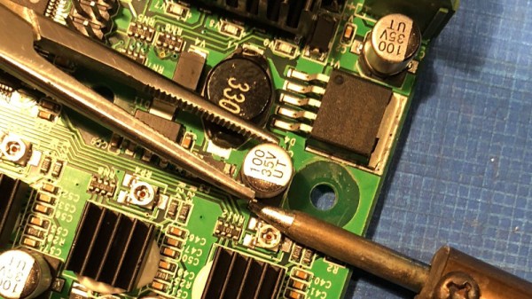
200KV Capacitor Uses Cake Pan And Bowl

[PhysicsGirl] posts videos that would be good to use in a classroom or homeschool environment. She recently showed a 200KV capacitor made from a cake pan, a bowl, and some other common items (see video, below).

One of the most interesting things about the project was how they charged the capacitor. A PVC pipe and some common hardware made a wand that they’d charge by rubbing a foam sleeve up and down against the dome formed by a metal bowl. We might have used a cat, but there’s probably some law against that.

To discharge, they used the end of the wand and were able to get a 10 cm spark. Based on the dielectric constant for air, they estimated that equated to a 200KV charge. They also discharged it through someone’s finger, which didn’t seem like a great idea.

We’ve talked about [PhysicsGirl’s] videos before. Granted, a lot of this won’t help the experienced hacker, but if you work with kids, they are a great way to make physics interesting and approachable. We wish she’d spent more time on the actual construction (you’ll need to slow it down to see all the details), though. If you really want a capacitor for your high voltage mad science, you might find these more practical. We’ve seen many homemade capacitors for high voltage.

Continue reading “200KV Capacitor Uses Cake Pan And Bowl”

Powering A Laptop With Supercapacitors

What do you do when you find a small horde of supercapacitors? The correct answer is a spectrum of dangerous devices ranging from gauss guns to quarter shrinkers. [Rinoa] had a less destructive idea: she’s replaced the battery in a laptop with a bank of supercapacitors.

The supercaps in question are 2.7 Volt, 500 Farad caps arranged in banks six for a total of about 3 watt-hours in each bank. The laptop used for this experiment is an IBM Thinkpad from around 1998. The stock battery in this laptop is sufficiently less advanced than today’s laptop batteries. Instead of using a microcontroller and SMBus in the battery, the only connections between the battery and laptop are power, ground, and connections for a thermocouple. This is standard for laptops of the mid-90s, and common in low-end laptops of the early 2000s. It also makes hacking these batteries very easy as there’s no associated microprocessors to futz around with.

With all the capacitor banks charged, the laptop works. It should – there isn’t a lot of intelligence in this battery. With one bank of six supercaps, [Rinoa] is getting a few minutes of power on her laptop. With a stack of supercaps that take up about the same volume as this already think Thickpad, [Rinoa] can play a few turns of her favorite late-90s turn-based strategy game. It’s not much, but it does work.

Check out [Rinoa]’s video below.

Continue reading “Powering A Laptop With Supercapacitors”

Disposable Camera Coil Gun!

Some of the most enjoyable projects tend to have the terrible drawback of also having the most potential to cause bodily harm, like getting zapped by the capacitor when digging into a disposable camera. But often — if you’re careful — this curiosity pays off and you wind up learning how to make something cool like this coil gun from a camera flash’s capacitor. This handheld launches a small nail, and is packed in a handheld form factor with a light switch trigger.

[LabRatMatt] dispels any illusions of potential harm upfront and then repeatedly urges caution throughout his detailed guide. He breaks down the physics at work while maintaining a lighthearted tone. This coil gun uses a capacitor and charging circuit ripped from a disposable camera — [LabRatMatt] decided to double up with another capacitor that he had on hand from a previous project. The coil was repurposed from an old doorbell, but make sure to use a few hundred windings if you make your own coil. A light switch ended up being suitable for a trigger since it is able to handle the voltage spikes.

When assembled, it almost looks like something you’d expect to see in a post-apocalyptic wasteland, but it works!

Continue reading “Disposable Camera Coil Gun!”

Getting A Handle On ESR With A Couple Of DIY Meters

Got a bunch of questionable electrolytic caps sitting in your junk bin? Looking to recap a vintage radio chassis? Then you might need to measure the equivalent series resistance of the capacitors, in which case this simple five-transistor ESR meter might come in handy.

Even if you have no need for an ESR meter, [W2AEW]’s video below is a solid introduction to how ESR is determined. The circuit itself comes from EEVBlog forum user [Jay-Diddy_B] and is about as simple as such a circuit can get. Two transistors form an oscillator that generates a square wave that drives a resistor bridge network. The two legs of the bridge feed matched common-emitter amps, one leg through the device under test. The difference in voltage between the two legs is read on a meter, and you have a quick and simple way to sort through the caps in your junk bin. [Jay-Diddy_B]’s circuit is only presented in breadboard form; no attempt was made to field a practical instrument. Indeed, [W2AEW] already built a home-brew ESR meter using hex inverters and op amps to which he compares the five-transistor circuit’s results. His intention here seems to be to clarify the technique of ESR measurement and evaluate an even simpler circuit than his. We think he’s done a good job on both counts.

We’ve featured plenty of [WA2AEW]’s work before, like this Michigan Mity-Mite transmitter or his primer on oscilloscopes. We really like his laid back style and the way he makes complex topics easy to understand. Check them out.

Continue reading “Getting A Handle On ESR With A Couple Of DIY Meters”

Build The Simplest Bipolar Power Supply

How many integrated circuits do you need to build up a power supply that’ll convert mains AC into a stable DC voltage? Would you believe, none? We just watched this video by [The Current Source] (embedded below), where he builds exactly that. If you’re in the mood for a very well done review of diode bridges as well as half- and full-wave rectifiers, you should check it out.

First off, [TCS] goes through the basics of rectification, and demonstrates very nicely on the oscilloscope how increasing capacitance on the output smooths out the ripple. (Hint: more is better.) And then it’s off to build. The end result is a very simple unregulated power supply — just a diode bridge with some capacitors on the output — but by using really big capacitors he gets down into the few-millivolt range for ripple into a constant load.

The output voltage of this circuit will depend on the average current drawn, but for basically static loads this circuit should work well enough, and the simplicity of just tossing gigantic capacitors at the problem is alluring. (We would toss in a linear regulator somewhere.)

Quibbling over circuit designs isn’t why you’re watching this video, though. It’s because you want to learn something. Check out the rest of his videos as well. [TCS] has only been at it a little while, but it looks like this is going to be a channel to watch.

https://www.youtube.com/watch?v=0iDCsrMM7M0

Measuring capacitance with wax dielectric

How To Measure The Dielectric Constant For DIY Capacitors

Every now and then you need to make your own capacitor. That includes choosing a dielectric for it, the insulating material that goes between the plates. One dielectric material that I use a lot is paraffin wax which can be found in art stores and is normally used for making candles. Another is resin, the easiest to find being automotive resin used for automotive body repairs.

The problem is that you sometimes need to do the calculations for the capacitor dimensions ahead of time, rather than just throwing something together. And that means you need to know the dielectric constant of the dielectric material. That’s something that the manufacturer of the paraffin wax that makes it for art stores won’t know, nor will the manufacturers of automotive body repair resin. The intended customers just don’t care.

It’s therefore left up to you to measure the dielectric constant yourself, and here I’ll talk about the method I use for doing that.

Continue reading “How To Measure The Dielectric Constant For DIY Capacitors”

Homemade Capacitors Of A Mad Scientist

Once upon a time I was a real mad scientist. I was into non-conventional propulsion with the idea of somehow interacting with the quantum vacuum fluctuations, the zero point energy field. I was into it despite having only a vague understanding of what that was and without regard for how unlikely or impossible anyone said it was to interact with on a macro scale. But we all had to come from somewhere, and that was my introduction to the world of high voltages and homemade capacitors.

And along the way I made some pretty interesting, or different, capacitors which I’ll talk about here.

Large Wax Cylindrical Capacitor

As the photos show, this capacitor is fairly large, appearing like a thick chunk of paraffin wax sandwiched between two wood disks. Inside, the lead wires go to two aluminum flashing disks that are the capacitor plates spaced 2.5cm (1 inch) apart. But in between them the dielectric consists of seven more aluminum flashing disks separated by plain cotton sheets immersed in more paraffin wax. See, I told you these capacitors were different.

I won’t go into the reasoning behind the construction — it was all shot-in-the-dark ideas, backed by hope, unicorn hairs, and practically no theory. The interesting thing here was the experiment itself. It worked!

I sat the capacitor on top of a tall 4″ diameter ABS pipe which in turn sat on a digital scale on the floor. High voltage in the tens of kilovolts was put across the capacitor through thickly insulated wires. The power supply contained a flyback transformer and Cockcroft-Walton voltage multiplier at the HV side. As I dialed up the voltage, the scale showed a reducing weight. I had weight-loss!

But after a few hours of reversing polarities and flipping the capacitor the other way around and taking plenty of notes, I found the cause. The weight-loss happened only when the feed wires were oriented with the top one feeding downward as shown in the diagram, but there was no weight change when the top wire was oriented horizontally. I’d seen high voltage wires moving before and here it was again, producing what looked like weight-loss on the scale.

But that’s only one of the interesting capacitors I’ve made. After the break we get into gravitators, polysulfide and even barium titanate.

Continue reading “Homemade Capacitors Of A Mad Scientist”