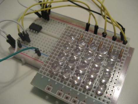
Visualizing LEDs For More Efficient Pin Packing

The archetypal “blink an LED” is a great starter project on any platform, but once the bug takes hold that quickly turns into an exploration of exactly how many LEDs a given microcontroller can drive. And that often leads to Charlieplexing. A quick search yields many copies of The Table describing how many LEDs can be driven by a given number of pins but that’s just the most rudimentary way to describe it. Way back in 2013 [M Rule] developed a clever trick to describe the number of LED matrices which can be driven by a Charlieplexed array of a given size that makes this process much more intuitive. The post may be old, but we promise the method is still fresh.

[M Rule] was specifically looking to drive those big, cheap single color LED matrices which are often used to make scrolling signs and the like. These parts are typically a matrix of LEDs with a row of common cathodes and one of common anodes. Internally they are completely dumb and can be driven by row/column scanning, or any other way a typical matrix can be controlled. The question is, given known matrix sizes, how many can be driven with a a number of Charlieplexed LED drive pins?
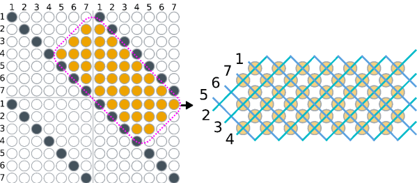
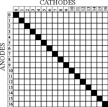
The first step is to visualize the 1D array of available pins as a 2D matrix, as seen to the right. Note each numbered pin is the same on the X and Y, thus the black exclusion zone of illegal drive pin combinations slicing across the graph (you can’t drive an LED connected to one pin twice). The trick, if one were to say it resides in a single place, would be titling the axis anode and cathode, representing two “orientations” the drive pins can be put in. With this diagram [M Rule] observed you can simply drop a matrix into the array. If it fits outside the exclusion zone, it can be driven by those pins!
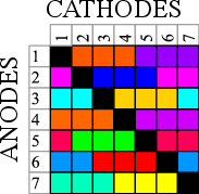
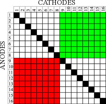
To the left is what this looks like with two 8×8 matrices, one connected between pins 1-8 and 9-16, the other connected between 9-16 and 1-8. This isn’t terribly interesting, but the technique works just as well with single LEDs and any size matrix, including 7-segment displays. Plus as long as an element doesn’t overlap itself it can wrap around the edges leading to some wild visuals, like 14 RGB LEDs on seven pins to the right.

The most extreme examples are pretty exotic. Check out [M Rule]’s post for the crown jewel; 18 pins to drive six 5×7 modules, six 7-segment displays, 12 single LEDs, and 18 buttons!

If this color coded diagram seems familiar, you may be remembering [openmusiclabs]’ excellent diagram describing ways to scan many of buttons. Or our coverage of another trick of matrix topology by [M Rule] from a few weeks ago.

Lateral Thinking For An Easier Charlieplex

In the practical world we live in, PCBs are often rectangles (or rectangles with rectangles, it’s just rectangles all the way down). When a designer goes to schematic capture things are put down on nice neat grid intersections; and if there isn’t a particular demand during layout the components probably go on a grid too. Routing even the nastiest fractal web of traces is mostly a matter of layers and patience. But if the layout isn’t being done in a CAD tool and needs to be hand assembled free-form this isn’t always as simple. [M Rule] had this very problem and discovered a clever solution, turning things diagonal.

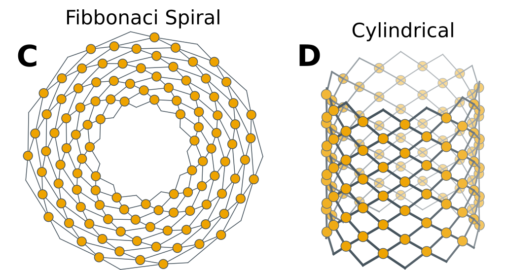
They changed the fitness criteria to the optimization problem that is controlling a lot of LEDs. Instead of minimum pins to drive the goal became “easiest assembly”, which meant avoiding wires snaking back and forth across the layout, a big source of frustration in a big Charlieplexed design. The observation was that if they turned the a rectilinear LED matrix by 45° and wrapped each connection around at the edges it formed what was essentially a large multiplexed matrix. The topology is pretty mind bending, so take a minute to study the illustration and build your mental model.

It looks a little strange, but this display works the same way a normal multiplexed display does but with the added benefit that each trace flows from one side to the other without turning back on itself at any point. To light any LED set the right row/column pair as source/sink and it turns on!

What if you actually need a rectangular display? Well that’s no problem, the matrix can be bent and smooshed as desired to change its shape. At the most extreme the possible display topologies get pretty wild! We’re sure to try thinking laterally next time we need to design an unusual display, maybe there is a more efficient matrix to be found.

Mini Retro PET Computer

There was a time that the Commodore PET was the standard computer at North American schools. It’s all-in-one, rugged construction made it ideal for the education market and for some of us, the PET started a life-long love affair with computers. [Ruiz Brothers] at Adafruit has come up with a miniature PET model run on a microcontroller and loaded up with a green LED matrix for a true vintage look.

While not a working model of a PET, the model runs on an Adafruit Feather M0 Basic Proto which is an Atmel ATSAMD21 Cortex M0 microcontroller and can display graphics on Adafruit’s 16×9 charlieplexed led matrix.The ATSAMD21 is the chip used in the Arduino Zero, so I’m sure we’ll see more of this chip in the future. Like all of the tutorials at Adafruit, this one is very detailed with step-by-step animated pictures to help you along. Obviously, you don’t need the exact hardware that they’re using, but if you’re putting in an order from Adafruit anyway, why not?

The plans for the 3D printed PET are available for free, so even if you don’t want to put their LED matrix and microcontroller in it, you can still print yourself out a great looking prop and 3D printing the PET will only use about a dollar’s worth of filament. Of course, while this is a cool retro model, if you have a Commodore PET lying around, you could probably do something else with it. We don’t, so that sound you hear is the sound of our 3D printer printing up the past.

Continue reading “Mini Retro PET Computer”

Charliplexed 7-Segment Display Takes Advantage Of PCB Manufacturers

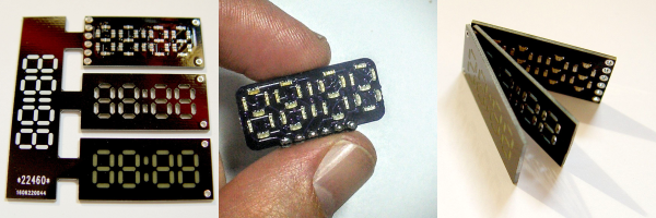
Cutting out precise shapes requires a steady hand, a laser cutter, or a CNC mill, right? Nope! All you need is PCB design software and a fabrication facility that’ll do the milling for you. That’s the secret sauce in [bobricius]’s very pleasing seven-segment display design.

His Hackaday.io entry doesn’t have much detail beyond the pictures and the board files, but we’re not sure we need that many either. The lowest board in the three-board stack has Charlieplexed LEDs broken out to six control pins. Next up is a custom-routed spacer board — custom routed by the PCB house, that is. And the top board in the stack is another PCB, this one left clear of copper where the light shines out.

We want to see this thing lit up! We’ve played around with using PCB epoxy material as a LED diffuser before ourselves, and it can look really good. The spacers should help even out the illumination within segments, while preventing bleed across them. Next step? A matrix of WS2812s with custom-routed spacers and diffusers. How awesome would that be?

Infinity Mirror Clock: There’s A Time Joke There Somewhere

Infinity Mirror Clock

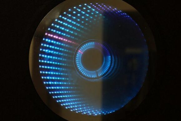
We don’t think we’ve seen an Infinity Mirror Clock before, but we love this new twist on an old favorite. Different colors distinguish between seconds, minutes and hours, and an additional IR sensor detects when someone is directly in front of the clock and switches the LEDs off, allowing it to be used as a normal mirror. This build is the work of [Dushyant Ahuja], who is no stranger to hacking together clocks out of LEDs. You can tell how much progress he’s made with the mirror clock by taking a glance at his first project, which is an impressive creation held together by jumbles of wire and some glue.

[Dushyant] has stepped up his game for his new clock, attaching an LED strip along the inside of a circular frame to fashion the infinity mirror effect. The lights receive a signal from an attached homemade Arduino board, which is also connected to a real-time clock (RTC) module to keep time and to a Bluetooth module, which allows [Dushyant] to program the clock wirelessly rather than having to drag out some cords if the clock ever needs an adjustment.

Stick around after the jump for a quick demonstration video. The lights are dazzling to watch; [Dushyant] inserted a stainless steel plate at the center of the circle to reflect the outer rim of LEDs. After a quick rainbow effect, it looks like the mirror enters clock mode. See if you can figure out what time it is. For a more step-by-step overview of this project, swing by his Instructables page.

Continue reading “Infinity Mirror Clock: There’s A Time Joke There Somewhere”

A Charlieplex Display And A Board Layout Tip

[Ben] is getting himself up to speed with microcontrollers. He jumped into the deep end by taking on this Charlieplex LED matrix build. As you can see after the break, he not only made the display work, but coded Conway’s game of life to run on the ATtiny85 that drives the device. What you see above is the prototype version that [Ben] used to make sure he had the hardware just right. He’s seeing the project through to a manufactured board and this is where the layout tip comes from. In order to make sure he had enough space for all of his components he printed out the board artwork, taped it to some Styrofoam, and then inserted all of the through-hole parts. Now he can be sure that physically the design works, we’ll keep our fingers crossed that everything is also kosher electrically.

Continue reading “A Charlieplex Display And A Board Layout Tip”

Intro To Charlieplexing

charlie

[sixerdoodle] sent us this nice firefly project that serves as an intro to charlieplexing. We’ve mentioned charlieplexing before, in our LED Life post and the Breath Controlled LED candles post. This project is quite simple and focues mainly on how to make a charlieplexed circuit work.

The goal was to create a tiny firefly bottle with SMD LEDs and as few wires as possible. In the video, after the break, it is hard to tell just how small this thing is until we see the battery. There are clear directions and fantastic pictures detailing exactly how to set up a charlieplexed circuit with 6 LEDs.

Continue reading “Intro To Charlieplexing”