If the workings of a mechanical timepiece give you a thrill, prepare to be blown away by this over-the-top astronomical clock.
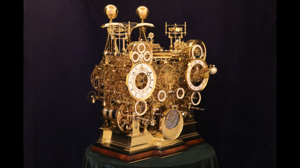
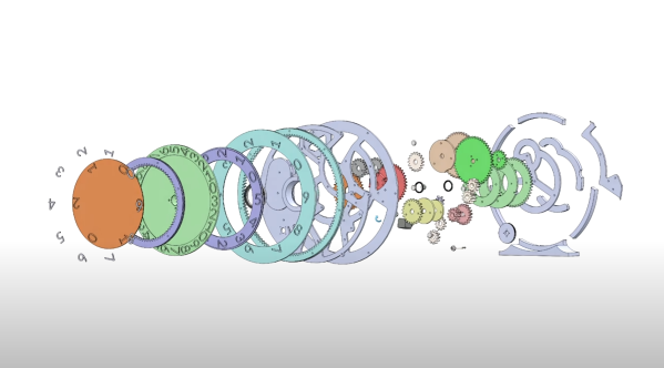
The horological masterpiece, which was designed by [Mark Frank] as his “dream clock”, is a riot of brass, bronze, and steel — 1,200 pounds (544 kg) of it, in fact, at least in the raw materials pile. Work on the timepiece began in 2006, with a full-scale mockup executed in wood by Buchannan of Chelmsford, the Australian fabricator that [Mark] commissioned to make his design a reality. We have a hard time explaining the design, which has just about every horological trick incorporated into it.
[Mark] describes the clock as “a four train, quarter striking movement with the fourth train driving the astronomical systems,” which sounds far simpler than the finished product is. It includes 52 “complications,” including a 400-year perpetual calendar, tide clock, solar and lunar eclipse prediction, a planisphere to show the constellations, and even a thermometer. And, as if those weren’t enough, the clock sports both a tellurion to keep track of the Sun-Earth-Moon system and a full orrery out to the orbit of Saturn, including all the major moons. The video below shows the only recently finished masterpiece in operation.
[Mark]’s dream clock has been under construction for the better part of two decades, and we applaud not just his design but his patience. The skeletonized construction reminds us of the Clickspring clock from a few years back; now seems like a great time to go back and binge-watch that whole series again.
Continue reading “An Astronomical Mechanical Clock, In More Ways Than One”
 Here at Hackaday, we pride ourselves on bringing you the very freshest of hacks. But that doesn’t mean we catch all the good stuff the first time around, and occasionally we get a tip on an older project that really should have been covered the first time around.


