Seven-Segment Flip Clock Display Finally Finished

Earlier this year, we mentioned in a Hackaday Links article that [Spencer Hamblin] was in the process of building a seven-segment flip clock. Well, it’s finally finished, and it looks great!

Vintage seven segment digits make up the display. These digits work the same way that flip-dot displays work – current through each segment’s coil creates a magnetic field which causes the segment to flip over. Current in the other direction creates the opposite magnetic field and flips the segment the other way. On these digits, there are three connections on the coils. The middle one is power and the other two are used to enable and disable the segment – ie., flip it one way or the other. To save on pins on the microcontroller, [Spencer] connected all the middle coil pins together on a digit. Each coil can be powered using a single pin on the microcontroller. Similarly, the segments for each digit are connected together as well, so one pin on the micro controls the same segment on each of the digits. The microcontroller in question is the AVR ATMega48.

There are two parts of the clock face left to do: AM/PM and whether the alarm is set or not. [Spencer] used a fifth digit, slightly offset, for those – the top and middle segments are used.

For the housing of the clock, [Spencer] used layers of offsetting colored wood. The wood (sapele and ash) were CNC cut and aligned. The back plate, also made from wood, holds buttons for setting the time and alarm, as well as some LEDs for what [Spencer] calls the “daylight alarm.” A capacitive sensor on the top of the unit (inside the wooden case) is used to turn the alarm off.

The result, after sanding and shellacing, looks amazing. [Spencer] nailed the art-deco look he was going for. There are plenty of pictures and the circuit designs, schematics and code are on [Spencer]’s Hackaday.io page, and you can find the Hackaday links post here. This is a complete log of a project we mentioned earlier on Hackaday, here, but there are other mechanical flip display clock projects, such as this DIY mechanical flip seven-segment prototype, or, you could create your own (really big) clock using this Lego mechanical seven-segment display.

via Reddit.

Color Changing Clock Uses PCB Digits

There’s an old saying, that you should do everything at least twice. Once to learn how to do it, and then a second time to do it right. Perhaps [Zweben] would agree, since he wasn’t satisfied with his first Neopixel clock and proceeded to build another one. One lesson learned: soldering 180 tiny solder joints isn’t much fun. This time, [Zweben] set out to make a printed circuit board and redesign the clock to make it easier to assemble.

The clock uses multiple copies of a single circuit board. The board holds Neopixel strips in a 7-segment arrangement. Each board can also hold all of the electronics needed to drive the clock. Only the first board gets the microcontroller and other circuits.

Continue reading “Color Changing Clock Uses PCB Digits”

A Minimalist Weather Clock With A Unique Display

If you’re looking for a home hub to display weather, time, and important family information, the formula is pretty simple: build yet another “magic mirror” project. We’re not complaining — magic mirrors look great. But if all you need is time and weather, this elegant pixel display is something just a little bit different.

Among his many criteria for the perfect hack, [Dominic] lists usefulness, visual appeal, and low cost. We’ll agree that his minimalist weather clock hits all those marks, and with the careful selection of a 16 x 32-pixel RGB display module, [Dominic] ended up giving back to the community by developing an Arduino driver for it. He points out that strips of Neopixels could have been used for the display, but they’d have ended up costing more, so the LED matrix was a sensible choice. A 3D-printed separator grid and a paper diffuser provide the proper pixelated look, and some simple animated icons display the two-day weather forecast. We find the time and temperature numerals a little hard to read, but it’s not bad considering the limited resolution of the display. And the case is a nice bit of woodworking too. Not a bad result for only €43.

We’re intrigued by the P10 LED matrix module [Dominic] used for this one. It might be a good choice for a word clock and weather station, or with his driver, a display for just about anything.

Over-Engineered Clock Uses No Less Than Five ESP32s

When [Proto G] enters into an Instructables contest whose only requirement is for the project to be wireless; he does so with style. Let’s put aside for a minute that he’s using a separate ESP32 board for each of the clock’s characters – that’s one for the hour, then one for the colon, one for the minutes and other colon and then the seconds. If you’re keeping count, that’s FIVE ESP32s. But like we said… put that aside and take into account that he’s using three different wireless communication protocols to make the five ESP32s get cozy with one another:

  1. His phone is connected to a cell tower.
  2. One of the ESP is connected to his phone to get the time.
  3. Two other ESPs connect to his phone and send minutes and seconds info to two more ESPs via the board’s internal communication protocol – ESPNOW

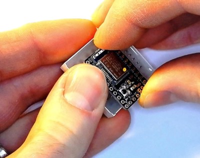
In case you’re wondering; the boards he’s using each have an OLED, battery, USB-to-serial converter and of course the ESP32. [Proto G] felt he could add some more complication to his project by crushing the programming connector on one of the boards with his chair. He had to break out the soldering iron and some jumper wire to make a quick but effective repair.

Be sure to check out his Instructables page for more great projects!

Modernizing A 170 Year Old Antique Grandfather Clock

Frankly, we let out a yelp of despair when we read this in the tip line “Antique Grandfather clock with Arduino insides“! But before you too roll your eyes, groan, or post snark, do check out [David Henshaw]’s amazing blog post on how he spent almost eight months working on the conversion.

Before you jump to any conclusions about his credentials, we must point out that [David] is an ace hacker who has been building electronic clocks for a long time. In this project, he takes the antique grandfather clock from 1847, and puts inside it a new movement built from Meccano pieces, stepper motors, hall sensors, LEDs, an Arduino and lots of breadboard and jumper wires while making sure that it still looks and sounds as close to the original as possible.

He starts off by building a custom electro-mechanical clock movement, and since he’s planning as he progresses, meccano, breadboard and jumper wires were the way to go. Hot glue helps preserve sanity by keeping all the jumper wires in place. To interface with all of the peripherals in the clock, he decided to use a bank of shift registers driven from a regular Arduino Uno. The more expensive DS3231 RTC module ensures better accuracy compared to the cheaper DS1307 or similar clones. A bank of RGB LEDs acts as an annunciator panel inside the clock to help provide various status indications. The mechanical movement itself went through several iterations to get the time display working with a smooth movement of the hands. Besides displaying time, [David] also added a moon phase indicator dial. A five-rod chime is struck using a stepper motor driven cam and a separate solenoid is used to pull and release three chime hammers simultaneously to generate the loud gong sounds.

And here’s the amazing part – he did all of this before laying his hands on the actual grandfather clock – which was shipped to him in California from an antique clock specialist in England and took two months to arrive. [David] ordered just the clock housing, dial/face and external parts, with none of the original inner mechanism. Once he received it, his custom clock-work assembly needed some more tweaking to get all the positions right for the various hands and dials. A clock like this without its typical “ticktock” sound would be pretty lame, so [David] used a pair of solenoids to provide the sound effect, with each one being turned on for a different duration to produce the characteristic ticktock.

At the end of eight months, the result – christened Judge – was pretty satisfying. Check the video below to judge the Judge for yourself. If you would like to see some more of [David]’s clockwork, check out Dottie the Flip Dot Clock and A Reel to Reel Clock.

Continue reading “Modernizing A 170 Year Old Antique Grandfather Clock”

Bluetooth Bedroom Clock!

When [decino]’s old bedroom clock finally bit the dust, he built himself a new one from scratch for fun and functionality.

Initially, he wanted to solder Adafruit NeoPixel lights onto four prototype boards, using a mini-USB for power and a DS1307 to keep the time. However, after soldering the board for the first digit and realizing that carrying on with the other three would be a huge pain, he switched to etching the boards instead — a far more efficient solution. In keeping with this time-saving mindset, he added a Bluetooth module that would allow him to update the clock from his phone whenever the DS1307 started dropping minutes or whenever daylight savings time is in effect.

Continue reading “Bluetooth Bedroom Clock!”

Hackaday Prize Entry: Global Positioning Clock

How do you get the attention of thousands of Hackaday readers? Build a clock! There are just so many choices to agonize over. Do you go with a crystal as a clock source, a fancy oven controlled crystal oscillator, or just mains voltage? Should you even think about putting a GPS module in a clock? All these are very interesting questions that encourage discussion or learning, and that’s what Hackaday is all about. Clocks are cool, and the engineering behind them is even cooler.

For one of [Nick]’s Hackaday Prize entries, he’s building a minimalist GPS clock. First up, the centerpiece of every clock, the display. There are eight seven-segment displays, two each for the hours, minutes, and seconds, and a smaller digit for tenths of a second. These displays are controlled by an ATXmega32E5, an upgrade on an earlier version of this project that only used an ATtiny and a MAX6951 LED driver.

The GPS wizardry is where this project gets really cool. [Nick] is using a SkyTraq Venus838LPx-T (that’s also available on a breakout board on Tindie). This GPS chip has a handy edge mount SMA connector to receive the signals from a GPS satellite, and has a bidirectional UART to dump the NMEA time codes and a PPS output. By combining the timecode, PPS output, and playing around with the timers on the microcontroller, [Nick] has a fantastically accurate clock that also looks great.