When you want to measure the length, breadth, or depth of an object, there are plenty of instruments for the job. You can start with a tape measure, move up to calipers if you need more precision, or maybe even a micrometer if it’s a really critical dimension. But what if you want to know how flat something is? Is there something other than a straightedge and an eyeball for assessing the flatness of a surface?
As it turns out, there is: a $15 webcam and a cheap laser level will do the job, along with some homebrew software and a little bit of patience. At least that’s what [Bryan Howard] came up with to help him assess the flatness of the gantry he fabricated for a large CNC machine he’s working on.
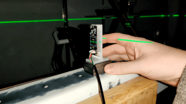
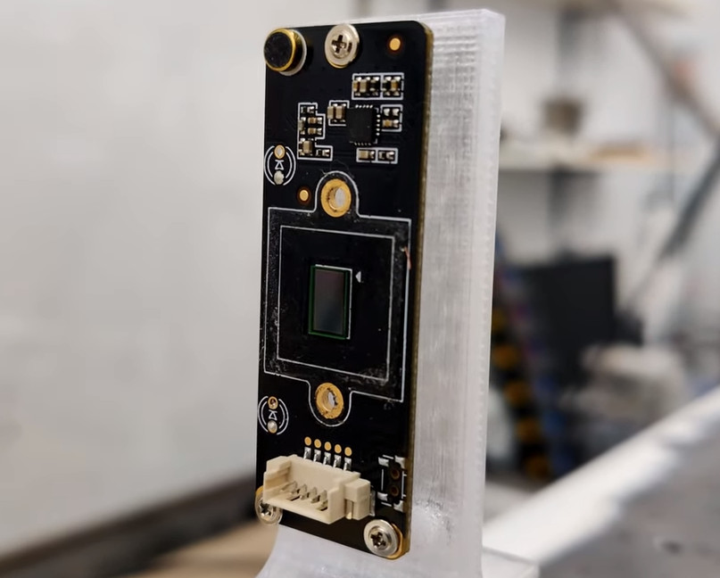 The gantry arm is built from steel tubing, a commodity product with plenty of dimensional variability. To measure the microscopic hills and valleys over the length of the beam, [Bryan] mounted a lens-less webcam to a block of metal. A cheap laser level is set up to skim over the top of the beam and shine across the camera’s image sensor.
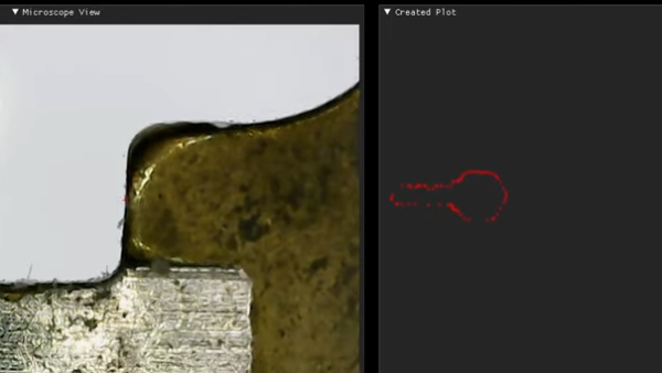
On a laptop, images of the beam are converted into an intensity profile whose peak is located by a Gaussian curve fit. The location of the peak on the sensor is recorded at various points along the surface, leading to a map of the microscopic hills and valleys along the beam.
As seen in the video after the break, [Bryan]’s results from such a quick-and-dirty setup are impressive. Despite some wobblies in the laser beam thanks to its auto-leveling mechanism, he was able to scan the entire length of the beam, which looks like it’s more than a meter long, and measure the flatness with a resolution of a couple of microns. Spoiler alert: the beam needs some work. But now [Bryan] knows just where to scrape and shim the surface and by how much, which is a whole lot better than guessing. Continue reading “Laser And Webcam Team Up For Micron-Resolution Flatness Measurements”