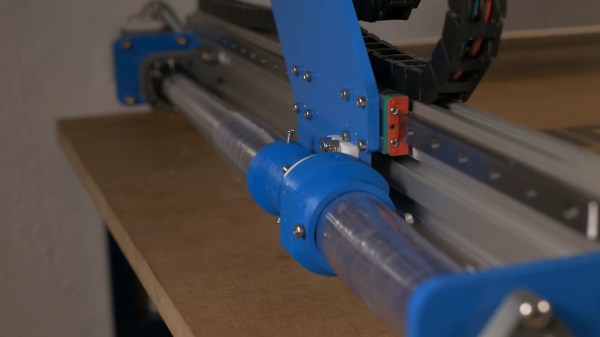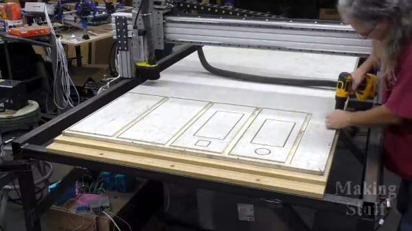
Many of us have spent the better part of a year on COVID-19 lockdown, and what do we have to show for it? Bit of progress on the Netflix queue? Maybe a (slightly) cleaned up garage or workshop? Not if you’re [Bob] of Making Stuff fame: he’s spent the last nine months working on a completely custom CNC router big enough to take a whole sheet of plywood.
The build is documented over a series of nearly a dozen YouTube videos, the first of which was put out all the way back in January of 2020. Seeing [Bob] heading to the steel mill to get his frame components with nary a mask in sight is a reminder of just how long he’s been working on this project. He’s also put together a comprehensive Bill of Materials on his website should anyone want to follow in his footsteps. Coming in at only slightly less than $4,000 USD, it’s certainly not a budget build. But then when we’re talking about a machine of this scale, nothing comes cheap.
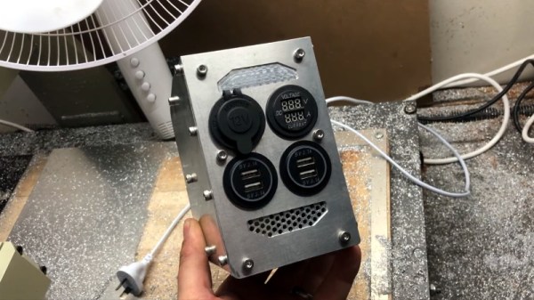
Even if you don’t build you own version of this router, it’s impossible to watch the build log and not get inspired about the possibilities of such a machine. In the last video we’re even treated to a bit of self-replicating action, as the jumbo CNC cuts out the pieces for its own electronics enclosure.
You can tell from the videos that [Bob] is (rightfully) proud of his creation, and isn’t shy about showing the viewer each and every triumph along the way. Even when things don’t go according to plan, there are lessons to be learned as he explains the problems and how they were ultimately resolved.
Of course, we know a home-built CNC router doesn’t need to cost thousands of dollars or take up as much space as a pool table. The average Hackaday reader probably has no need of a monster like this, and wouldn’t have anywhere to keep it even if they did. But that doesn’t mean we can’t look on with envy as we wait to see what kind of projects [Bob] churns out with such an incredible tool in his arsenal.
 usually to move a tool head in such a way as to make something. Tons of systems have been built around it, including early Makerbot printers.