Wireless IPod Charger Built From Scratch

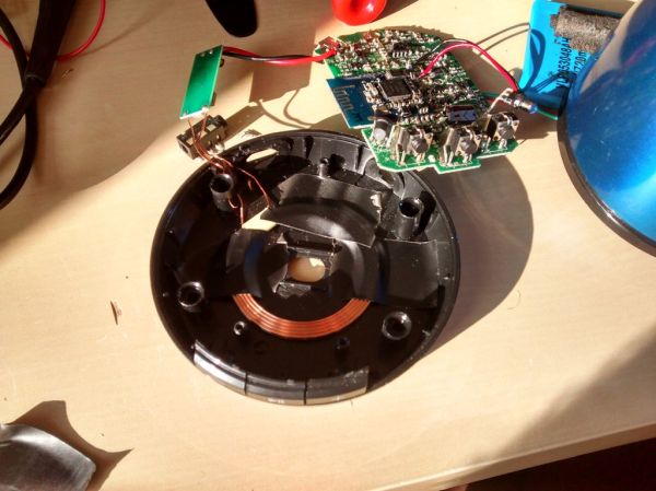
Despite the obvious use of a lot of wire, this project is actually a wireless charging system. [Jared] built it as a way to explore the concepts behind transferring power inductively. Alternating current on one of the white coils induces current on the other. This is then rectified, and regulated for use as a 5V charger. In this case it powers his iPod, but any USB device should work with the setup.

The transmitter uses the power supply from an old laptop as a source. Some filtering and a couple of MOSFETS are responsible for generating the AC current on the transmitting coil. The receiving coil feeds the bridge rectifier. In the writeup that voltage is fed to a 7805 regulator to provide a stable 5V output. However, in the video demo after the break [Jared] shows off the boost converter that he uses on his improved circuit. This way if the voltage drops due to poor alignment of the coils it will still be able to provide a steady output.

We’ve seen the same coil concept used to add wireless charging to cellphones too.

Continue reading “Wireless IPod Charger Built From Scratch”

mot-salvaging

Tutorial Series Shows You Everything You Need To Salvage Transformers From Microwaves

Transformers certainly have a tendency to increase the cost of any project, especially if you need a large transformer to get the job done. Microwave ovens are great sources of free transformers, though they are not always in the shape required for your next build.

[Matt] put together three great tutorial videos covering the basics of salvaging Microwave Oven Transformers (MOTs), that anyone new to the process should watch before giving it a go. The first video covers MOT removal and disassembly, which is a time consuming yet easy process providing you follow [Matt’s] pointers.

The second video delves into transformer theory, and discusses how to achieve optimal performance when rebuilding an MOT or hand wrapping coils to fit your project specs. The third video in the series follows [Matt] as he rebuilds one of the salvaged transformers, documenting his pitfalls and successes along the way.

If you haven’t given much thought to salvaging MOTs, we definitely recommend taking a bit of time to watch the video series in full – it’s definitely worth it.

You can see the first video in the series after the jump – the rest can be found via the YouTube link above.

Continue reading “Tutorial Series Shows You Everything You Need To Salvage Transformers From Microwaves”

Arduino Boards Control Cheap Clockworks Via Coil Injection

Here’s a couple of clocks that use Arduino boards to control inexpensive clockworks. The concept is quite simple, and perhaps best outlined by [Matt Mets’] article on the subject. As it turns out, these clockworks are driven by a coil, forming a device that is quite similar to a stepper motor. If you solder a wire onto each end of the electromagnetic coil and hook those to a microcontroller, you can alter the speed at which the clock ticks. Just drive one pin high and the other low, then reverse the polarity for the next tick.

The clock you see on the right (translated) is a store-bought cheapy. The Arduino barely visible at the bottom of the image is sending pulses once every second. But as you can see in the video after the break, holding down a button will fast-forward through time. [Sodanam] posted his code as well as pictures of the hardware hack itself.

To the left is a horse of a different color. It’s a clock modeled after the Weasley household clock from the Harry Potter books. The clockwork trick is the same, but the Arduino uses GPS data and NOAA weather information to set the status.

Continue reading “Arduino Boards Control Cheap Clockworks Via Coil Injection”

Simple FM Transmitter That Shows Off Its Own Circuitry

[Sean Michael Ragan] built this FM transmitter which shows off its circuitry via a clear plastic dome. The device is electrically identical to one we looked at in September. That version championed a construction method that used small squares of copper clad as solder points which were each super-glued to a large copper-clad platform serving as a ground plane. [Sean] is using a printed circuit board that was laid out by Sonodrome. You can check out their own glass-jar transmitter build where the board artwork is available for download.

One of the tips we enjoyed from [Sean’s] step-by-step build is the coil wrapping. He used the threads of a 1/4-20 bolt to guide copper wire as he wrapped a total of four turns. Once the bending is done, just unthread the bolt to separate it from the coil and gently stretch the wire for a 12mm distance between the two leads. Not only is this visually pleasing, but it will help with transmission clarity.

Fabric Speaker

The theory behind speaker operation is pretty simple. There’s a coil that is attached to some type of diaphragm and a permanent magnet. When electrical signals pass through the coil a magnetic field is generated, and that field’s interaction with the permanent magnet causes the diaphragm to vibrate and create sound. But we’ve always assumed that the vibrating material must be stretched tight for this to work. [Hannah Perner-Wilson] proved us wrong by making this speaker out of fabric. It uses conductive tape as the coil on a heavy piece of canvas. The permanent magnet is resting on a table and for the demonstration the fabric is just laid on top.

Check out the video after the break to hear the sounds generated by this device as well as a design that uses conductive thread instead of tape. This gets us wondering if what we’re hearing is the result of the magnet vibrating against the tabletop? Let us know your thoughts, and if you’ve got any information about the paper-backed circuit (seen at 0:04 into the video) driving the speakers we’d love to hear about that too.

Continue reading “Fabric Speaker”

Domino Clock Uses An Electromechanical Display

This clock concept uses big dominos with changing faces to display the time. As far as we can tell they haven’t made it through to a finished product yet, but we loved the explaination of the engineering that went into the prototype. After the break you can watch [Eric] explain how he accomplished the design requirements of a slowly changing digit that uses no power to keep its state, which also uses low-power when changing state. To accomplish this he designed a flipping circle that stays put in both the white and black positions once set. When it’s time to change the digits, a coil is energized to push against a magnet in what he calls a single poled motor. Whatever the name, we want to build one ourselves!

Continue reading “Domino Clock Uses An Electromechanical Display”