Balanced Design And How To Know When To Quit Optimizing

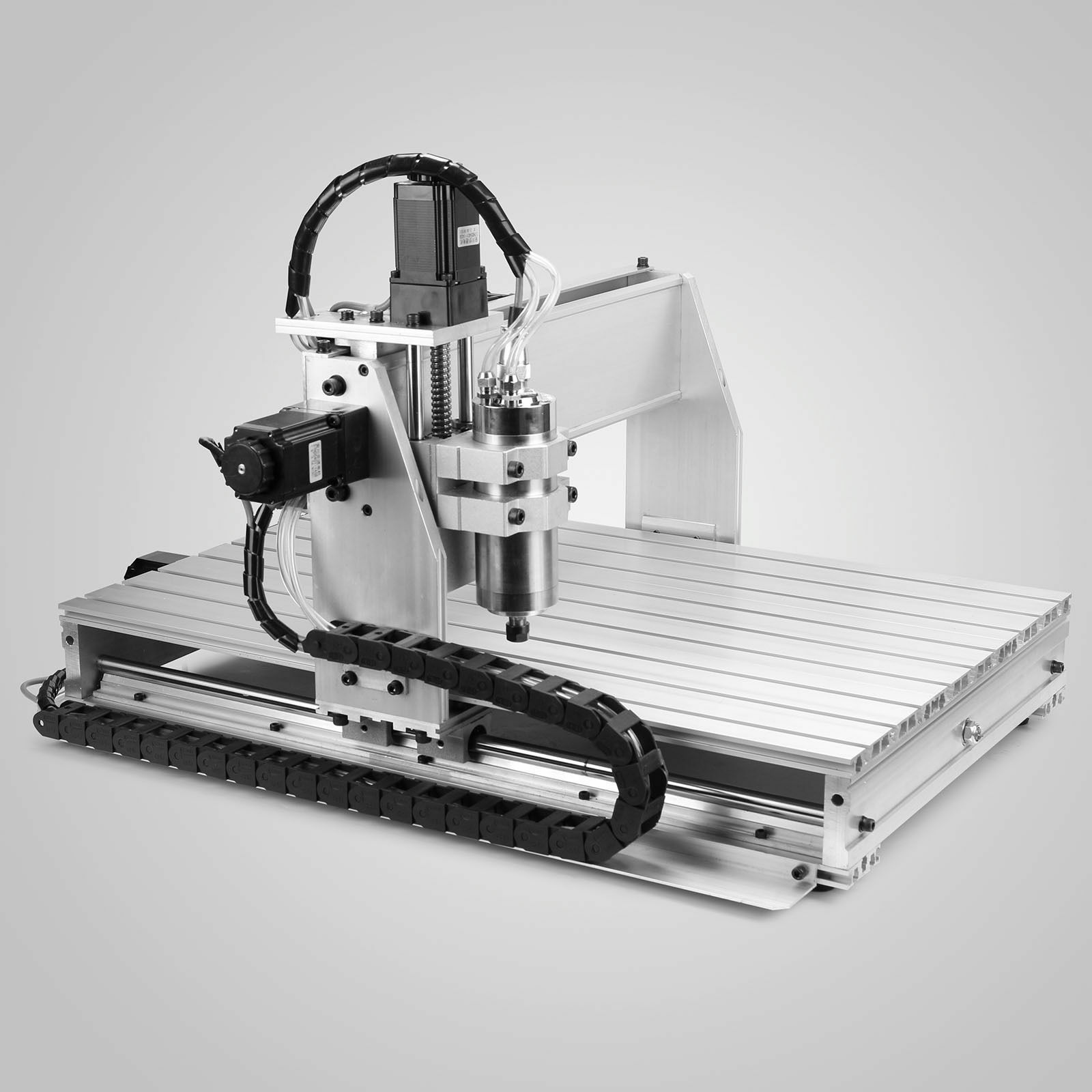
I got a relatively inexpensive 6040 CNC machine, and have been spending most weekends making the thing work, and then cutting stuff, learning the toolchain, and making subsequent improvements. Probably 90% of my machine time has been on making improvements. It’s not that the machine was bad — I got the version with ballscrews and a decently solid frame — but it’s that it somehow didn’t work together as a whole. It’s just an incredibly unbalanced design.

Let’s start with the spindle motor. It’s a 2.2 kW water-cooled beast that is capable of putting tons of work into a piece and spinning at very high speed. Yet to keep up with the high speed spindle, the motors that move it around would have to be capable of high speeds as well — it’s a feeds and speeds thing if you’re not a CNC geek. And they can’t. Instead, the stepper motors that came with the kit are designed for maximum force at low speeds. Which can make sense for some machines, but for one with a slightly flexible X-axis like this one, that’s wasted as well. The frame just can’t handle the low-end grunt that the motors are capable of, so it can’t take advantage of the spindle’s power either. The design is all over the place.

Over the last two months’ of weekends, I’ve been going through this iterative procedure of asking “what is my limiting factor right now?”, working on fixing that thing up, running it some, and then asking the question again. And it’s a good general procedure, and I believe that it’s getting me to the machine I want at the minimum cost of time, money, and effort.

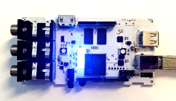
At first, it was the driver hardware/software with its emulated USB parallel port, so I swapped out the controller for an Arduino running GRBL, soldered directly to the DB-25 that comes out of the back. At least it can put out pulses fast enough to order the motors around, but they would still stall out at high speeds. Swapping the stepper motors out for a high-speed pair only cost me €40, which makes you wonder why they didn’t just put the right motors on in the first place. The machine now travels fast enough to make use of the high-speed spindle, and I’m flying through plywood and plastics without leaving burn marks. It’s a huge win for not much money.

The final frontier is taking big bites out of aluminum. The spindle can do it, but I fear I’m up against the frame’s rigidity on the X-axis. For whatever reason, they went with unsupported rods on the X, which are significantly more flexible than an axis that’s backed up by more metal. And this is where the limiting factor may actually be my time and patience, rather than money. I just can’t bear to disassemble and reassemble the thing again. So for now, it’s going to be small nibbles, taking advantage of the machine’s speed, if not yet the spindle’s full horsepower.

But it’s odd, because this machine is a bundle of good parts. It’s just that they haven’t been chosen to work together optimally; the frame doesn’t work with the stepper motors, which don’t work with the spindle. If they went through my procedure of saying “what’s the limiting factor?” they could have saved themselves €100 by just shipping it with a wimpier spindle, which would have been a balanced, if anemic, machine. Or they could have built it with the right motors for more speed. Or supported rails for more grunt. Or both!

I’ll never know why they quit optimizing their design when they did. Maybe they never got past the slow USB/parallel port speed? But I’m near the end of my path, and I can tell because the limiting ingredient isn’t a simple upgrade, or even mere money anymore, but my own willpower.

How can you tell when you’re at the top of a mountain in a dense fog? A step you take in any direction would lead you downhill. How can you tell when you’re satisfied with a project’s state? When you don’t have the need, or desire, to undertake the next most obvious improvement.

Free To Good Home: FPGA Supercharged Audio/Video Synthesizer

Audio and video synthesizers have been around for decades, and are pretty much only limited by one’s willingness to spend money on them.  That is, unless you can develop your own FPGA-supercharged synthesizer to really get a leg up on the consumer-grade components. Of course, as [Julian] found out in this four-year project, you tend to pay for it anyway in time spent working on your projects.

[Julian] has actually decided to stop working on the project and open-source it to anyone who wants to continue on. He has already finished the PCB layout on a gargantuan 8-layer print, done all of the routing and parts selection, and really only needed to finish testing it to complete the project. It’s powered by the Xilinx Zynq and is packed with features too: HDMI, DDR3 ram, USB, a handful of sensors, and an Arduino Uno-style header to make interfacing and programming a breeze.

While we’re sympathetic with setting aside a project that we’ve worked so hard on, with most of the work done on this one it should be pretty easy to pick up and adapt for anyone interested in carrying the torch. If you were hoping to wet your whistle with something with fewer PCB layers, though, we’ve seen some interesting (but slightly simpler) video synthesizers made out of other unique hardware as well.


The Right Tools For The Job

We’re knee-deep in new microcontrollers over here, from the new Raspberry Pi Pico to an engineering sample from Espressif that’s right now on our desk. (Spoiler alert, review coming out Monday.) And microcontroller peripherals are a little bit like Pokemon — you’ve just got to catch them all. If a microcontroller doesn’t have 23 UARTS, WiFi, Bluetooth, IR/DA, and a 16-channel 48 MHz ADC, it’s hardly worth considering. More is always better, right?

No, it’s not. Chip design is always a compromise, and who says you’re limited to one microcontroller per project anyway? [Francesco] built a gas-meter reader that reminded to think outside of the single-microcontroller design paradigm. It uses an ATtiny13 for its low power sleep mode, ease of wakeup, and decent ADCs. Pairing this with an ESP8266 that’s turned off except when the ATtiny wants to send data to the network results in a lower power budget than would be achievable with the ESP alone, but still gets his data up into his home-grown cloud.

Of course, there’s more complexity here than a single-micro solution, but the I2C lines between the two chips actually form a natural division of work — each unit can be tested separately. And it’s using each chip for what it’s best at: simple, low-power tasks for the Tiny and wrangling WiFi on the ESP.

Once you’ve moved past the “more is better” mindset, you’ll start to make a mental map of which chips are best for what. The obvious next step is combination designs like this one.

Run The Math, Or Try It Out?

I was reading Sonya Vasquez’s marvelous piece on the capstan equation this week. It’s a short, practical introduction to a single equation that, unless you’re doing something very strange, covers everything you need to know about friction when designing something with a rope or a cable that has to turn a corner or navigate a wiggle. Think of a bike cable or, in Sonya’s case, a moveable dragon-head Chomper. Turns out, there’s math for that! Continue reading “Run The Math, Or Try It Out?”

Death Of The Serial Squid: When Do You Give Up?

While searching for a connector recently, I revisited an old project of mine called the Serial Squid. This was to have been my first open-source hardware design. After completing the entire design, PCB, BOM, and preparing for a crowd-funded campaign, I eventually gave up for reasons discussed below, I’ve always thought of this as a failure, but on further reflection I see it in a new light. There were some good lessons learned along the path to abandonment.

When do you let go?  When should you push through? Continue reading “Death Of The Serial Squid: When Do You Give Up?”

Label Your Shtuff!

Joshua Vasquez wrote a piece a couple of weeks ago about how his open source machine benefits greatly from having part numbers integrated into all of the 3D printed parts. It lets people talk exactly about which widget, and which revision of that widget, they have in front of them.

Along the way, he mentions that it’s also a good idea to have labels as an integrated part of the machine anywhere you have signals or connectors. That way, you never have to ask yourself which side is positive, or how many volts this port is specced for. It’s the “knowledge in the head” versus “knowledge in the world” distinction — if you have to remember it, you’ll forget it, but if it’s printed on the very item, you’ll just read it.

I mention this because I was beaten twice in the last week by this phenomenon, once by my own hand costing an hour’s extra work, and once by the hand of others, releasing the magic smoke and sending me crawling back to eBay.

The first case is a 3D-printed data and power port, mounted on the underside of a converted hoverboard-transporter thing that I put together for last year’s Chaos Communication Congress. I was actually pretty proud of the design, until I wanted to reflash the firmware a year later.

I knew that I had broken out not just the serial lines and power rails (labelled!) but also the STM32 SWD programming headers and I2C. I vaguely remember having a mnemonic that explained how TX and RX were related to SCK and SDA, but I can’t remember it for the life of me. And the wires snake up under a heatsink where I can’t even trace them out to the chip. “Knowledge in the world”? I failed that, so I spent an hour looking for my build notes. (At least I had them.)

Then the smoke came out of an Arduino Mega that I was using with a RAMPS 1.4 board to drive a hot-wire cutting CNC machine. I’ve been playing around with this for a month now, and it was gratifying to see it all up and running, until something smelled funny, and took out a wall-wart power supply in addition to the Mega.

All of the parts on the RAMPS board are good to 36 V or so, so it shouldn’t have been a problem, and the power input is only labelled “5 A” and “GND”, so you’d figure it wasn’t voltage-sensitive and 18 V would be just fine. Of course, you can read online the tales of woe as people smoke their Mega boards, which have a voltage regulator that’s only good to 12 V and is powered for some reason through the RAMPS board even though it’s connected via USB to a computer. To be honest, if the power input were labelled 12 V, I still might have chanced it with 18 V, but at least I would have only myself to blame.

Part numbers are a great idea, and I’ll put that on my list of New Year’s resolutions for 2021. But better labels, on the device in question, for any connections, isn’t even going to wait the couple weeks until January. I’m changing that right now.

Diaphragm Air Engine

One of the tricky parts of engineering in the physical world is making machines work with the available resources and manufacturing technologies. [Tom Stanton] has designed and made a couple of air-powered 3D printed engines but always struggled with the problem of air leaking past the 3D-printed pistons. Instead of trying to make an air-tight piston, he added a rubber membrane and a clever valve system to create a diaphragm air engine.

This GIF is worth 115 words

A round rubber diaphragm with a hole in the center creates a seal with the piston at the top of its stroke. A brass sleeve and pin protrude through the diaphragm, and the sleeve seals create a plug with an o-ring, while the pin pushes open a ball which acts as the inlet valve to pressurize an intermediate chamber. As the piston retracts, the ball closes the inlet valve, the outlet valve of the intermediate chamber is opened, forcing the diaphragm to push against the piston. The seal between the piston and diaphragm holds until the piston reaches its bottom position, where the pressurized air is vented past the piston and out through the gearbox. For full details see the video after the break.

It took a few iterations to get the engine to run. The volume of the intermediate chamber had to increase and [Tom] had to try a few different combinations of the sleeve and pin lengths to get the inlet timing right. Since he wanted to use the motor on a plane, he compared the thrust of the latest design with that of the previous version. The latest design improved efficiency by 366%. We look forward to seeing it fly! Continue reading “Diaphragm Air Engine”