What can one expect from 3D printing an 8″ Newtonian telescope? [Molly Wakeling] shares her thoughts after doing exactly that. The performance was on par with any solid 8″ telescope, but in the end it wasn’t really any cheaper than purchasing a manufactured unit. Does that mean it wasn’t worth it? Not at all!
 [Molly] makes the excellent observation that the process of printing and building one’s own telescope is highly educational and rewarding. Also, the end result is modular, user-serviceable, and customizable in a way that many commercial offerings can only dream of. It’s a great conversation starter with other enthusiasts, as well!
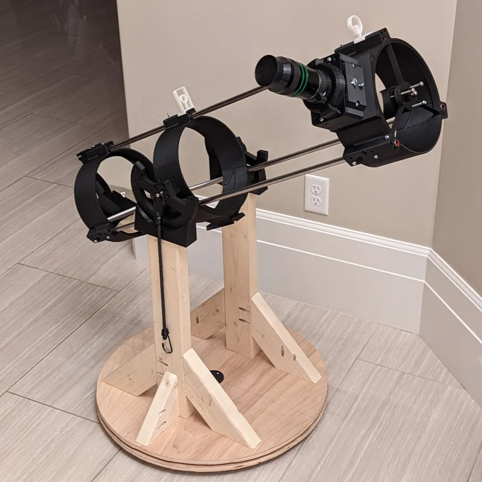
[Molly] printed the 203 Leavitt design (3d models available on Printables) which is an 8″ Newtonian telescope. This telescope design uses a concave parabolic mirror (a significant part of the expense) at the back of the tube to gather and focus light, and a small flat mirror near the front of the tube reflects this light to an eyepiece on the side. The wood stand makes things convenient, and we like the elastic tie-down used as a simple way to put tension on the mounts.
Do you find yourself intrigued but would prefer to start a little smaller and cheaper? Good news, because the same designer of the 203 Leavitt has a very similar design we happen to have featured before: the 114 Hadley. It features easily obtainable, lower-cost optics which perform well and can be easily ordered online, making it a great DIY starter telescope.