Staking and potting are not often used in the hobby electronics world, not really entering to the common vernacular. However, everyone who’s ever busted out a glue-gun to convince that dang wire that keeps coming loose to stay has done it.
However, as [Sean Thomas] touches on, staking is not necessarily as easy as a dob of hot glue. There is a method to the madness. [Sean] gives some examples in pictures, but also directs people to the excellent NASA standard methods for staking. It’s surprising how many unintuitive caveats there are to the proper technique.
Potting, or covering everything in epoxy forever, is a great way to get a waterproof, unserviceable, and practically mechanically invincible circuit. The big challenge in potting is picking the right material. A soft silicone, for example, might transfer an unexpected force to an unexpected section of the circuit and cause a mechanical failure. A nice hard epoxy may be too insulating and cause a thermal failure. The standard RTV from the big box store has acetic acid that will eat your components.
These two techniques that come in handy when you need them and worth the bit of reading it takes to get familiar. Have you used either in your own workshop? Let us know the application and the material/techniques you have tried in the comments below.
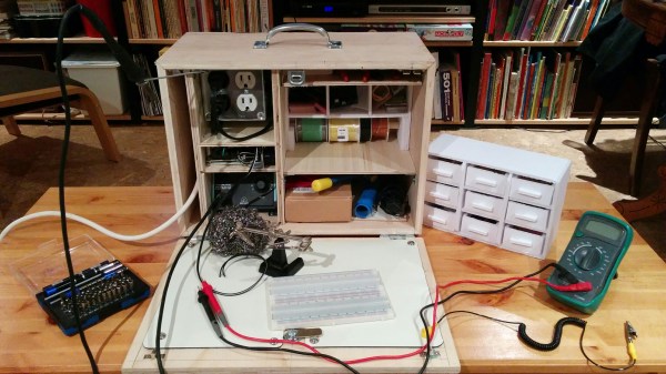
Making on the go is sometimes required in today’s busy lives, and if you find yourself traveling — say, off to university like [ZSNRA] — then a convenient solution is required. To that end, a portable electronics workbench was built in the shape of a relatively nondescript plywood box.
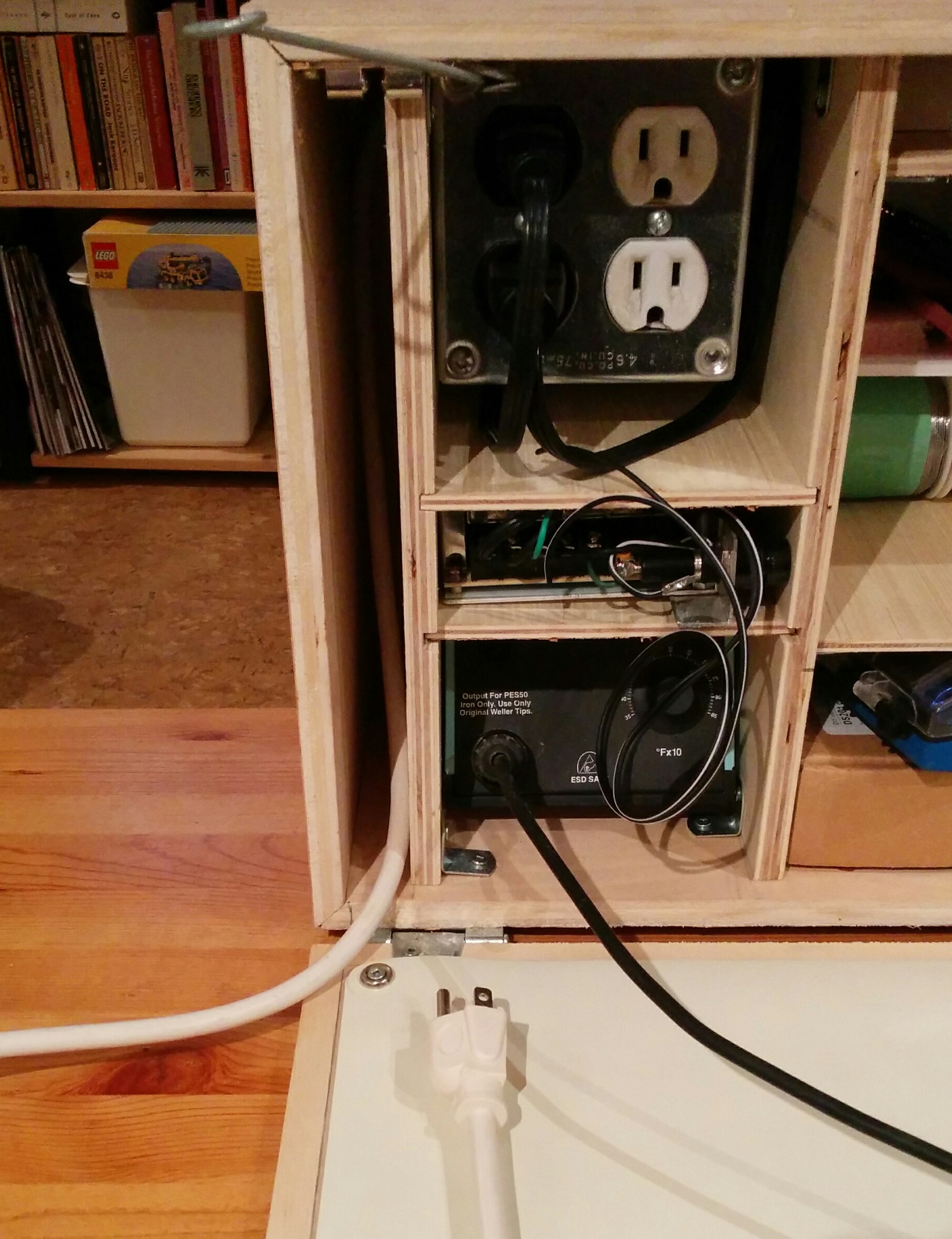
Plywood and foam-core are the main materials used in building this maker’s bug-out box, with two fir runners along the bottom so the case is not resting on the hinges. Inside, [ZSNRA] has packed a staggering amount of hardware which results in an 11kg suitcase.
Here goes — deep breath now: wires, solder, resistors, transistors, capacitors, diodes, clips, switches, logic chips, non-logic chips, an Arduino, ATmegas, fuses, pliers, wire strippers and cutters, angle cutters, tweezers, a 66-piece screwdriver set, a desoldering pump, 12 needle files, a hacksaw blade, a multi meter, oscilloscope, power source, four outlets built into the case(!), steel wool, a third hand, a soldering station, two handbooks, and a breadboard.
Whew.
The work surface is an ESD mat on the inside of the case’s front face that is comfortable enough to work with, though we are surprised that it doesn’t also fold out somehow to create an even larger work-space.
For an elegant — if slightly less mobile — workbench solution, check out The Tempel. Now if you’re looking for ideas on how and what to carry we still think [Kenji Larsen] has the ultimate hacking kit.
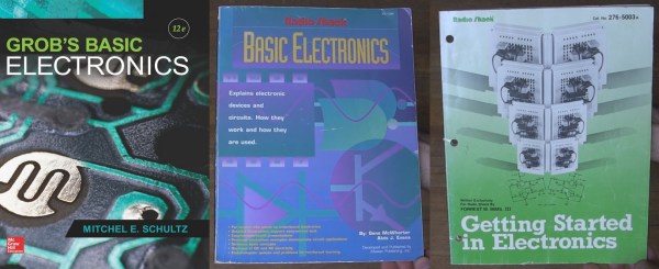
I learned some basic electronics in high school physics class: resistors, capacitors, Kirchhoff’s law and such, and added only what was required for projects as I did them. Then around 15 years ago I decided to read some books to flesh out what I knew and add to my body of knowledge. It turned out to be hard to find good ones.
The electronics section of my bookcase has a number of what I’d consider duds, but also some gems. Here are the gems. They may not be the electronics-Rosetta-Stone for every hacker, but they are the rock on which I built my church and well worth a spot in your own reading list.
Grob’s Basic Electronics
Grob’s Basic Electronics 12th Edition
Grob’s Basic Electronics by Mitchel E Schultz and Bernard Grob is a textbook, one that is easy to read yet very thorough. I bought mine from a used books store. The 1st Edition was published in 1959 and it’s currently on the 12th edition, published in 2015. Clearly this one has staying power.
I refer back to it frequently, most often to the chapters on resonance, induction and capacitance when working on LC circuits, like the ones in my crystal radios. There are also things in here that I couldn’t find anywhere else, including thoroughly exhaustive online searches. One such example is the correct definitions and formulas for the various magnetic units: ampere turns, field intensity, flux density…
I’d recommend it to a high school student or any adult who’s serious about knowing electronics well. I’d also recommend it to anyone who wants to reduce frustration when designing or debugging circuits.
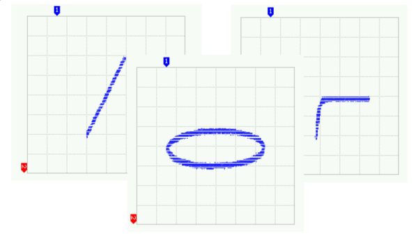
Series-Resonance calculations
Series-Resonance schematic
You can find the table of contents here but briefly it has all the necessary introductory material on Ohm’s and Kirchhoff’s laws, parallel and series circuits, and so on but to give you an idea of how deep it goes it also has chapters on network theorems and complex numbers for AC circuits. Interestingly my 1977 4th edition has a chapter on vacuum tubes that’s gone in the current version and in its place is a plethora of new ones devoted to diodes, BJTs, FETs, thyristors and op-amps.
You can also do the practice problems and self-examination, just to make sure you understood it correctly. (I sometimes do them!) But also, being a textbook, the newest edition is expensive. However, a search for older but still recent editions on Amazon turns up some affordable used copies. Most of basic electronics hasn’t changed and my ancient edition is one of my more frequent go-to books. But it’s not the only gem I’ve found. Below are a few more.
[Jason Jones] has always wanted a curve tracer for his home shop. When he was starting out in electronics he fell in love with a machine called a Huntron Tracker 2000. This machine would feed a sine wave into a circuit on one side and plot a XY graph on the other.
[Jason] figured that with a modern microcontroller such a device could be build simply and cheaply for around $15 dollars. With that requirement in mind he set out to build it. He selected a PIC24F16KM202 for the brain and got to work.
The write-up is really great. It’s rare that someone puts every step of their development and design thinking into writing. Some have argued that this is the only true way to have an OSHW hardware project. The series covers everything from the initial requirements and parts selection to the software development and eventual testing of the device.
[Jason] managed to build a pretty capable little curve tracer in the end. We really enjoyed it when he used the tracer to debug the tracer.
Chris Gammell is a guy that should need no introduction around these parts. He’s a co-host on The Amp Hour, and the guy behind Contextual Electronics, a fabulous introduction to electronics and one of the best ways to learn KiCad. If you want to talk about the pedagogy of electronics, this is the guy you want.
Chris’ talk at the Hackaday | Belgrade conference was on just that – the pedagogy of electronics. Generally, there are two ways to learn how to blink an LED. The first, the bottom-up model taught in every university, is to first learn Ohm’s law, resistance, current, voltage, solve hundreds of resistor network problems, and eventually get around to the ‘electrons and holes’ description of a semiconductor. The simplest semiconductor is a diode, and sometime in the sophomore or junior year, the student will successfully blink a LED.
The second, top-down method is much simpler. Just wire up a battery, resistor, switch, and LED to a breadboard. This is the top-down model of electronics design; you don’t need to know everything to get it to work. You don’t need to do it with a 555, and you certainly don’t have to derive Maxwell’s equations to make something glow. Chris is a big proponent of the top-down model of learning, and his Belgrade talk is all about the virtues of not knowing everything.
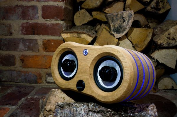
This is fresh on the heels of another hack that used similar construction methods to build a “magic” wood lamp. [Nick] takes it a step further, though. His case is precisely machined in white oak and stuffed with the latest China has to offer: a bank of lithium-ion batteries, a DC-DC converter to power the amplifier, and a Bluetooth module. After some sanding, the speakers look professional alongside the blue light features hiding behind the polycarbonate rings.
Of course you’ll want to visit the project site for all the details of how [Nick] built his speaker case. He does admit, however, that the electronics are fairly inefficient and need a little work. All in all though, it’s a very refined set of speakers that’ll look great on a bookshelf or on a beach, workshop bench, or anyplace else that you could take them.
As a fresh-faced electronic engineering student while the first Gulf War was raging in a far-off desert, I learned my way through the different families of 74 logic at a university in the North of England. 74LS was the one to use, the story went, because it’s quick and doesn’t use much power. At the time, there was an upstart on the scene: 74HC. Now that’s really quick. New. Exotic, even.
Thus an association was formed, when you want a quick logic function then 74HC is the modern one to go for. It could have been a lifelong love affair, but over twenty years, after many factors of speed increases and some RF tricks with gates we wouldn’t have dreamed of back then, it’s over. There is a whole world of newer logic families to choose from, and while HC is still good at what it does, it’s well past time to admit that it may just have been superseded.
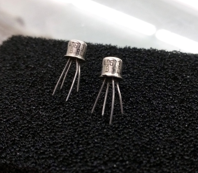
40673s, probably now worth more by weight than anything else on four legs. (Thanks are due to [Brandon Dunson] and Tanner Electronics) A tendency to cling to the past with logic families is pretty harmless. Like [Adam Fabio]’s TIP power transistors they’re pretty cheap, still very much in production, and still do most jobs demanded of them excellently. But what prompted this piece was a far more egregious example of an old component still being specified: the RCA 40673 dual-gate MOSFET. Launched in the mists of time when dinosaurs probably still roamed the earth, this static-sensitive four-pin TO72 found a home in a huge variety of RF amplifiers, oscillators, and mixers. It worked well, but as you might expect better devices came along, and the 40673 was withdrawn some time in the 1980s.
Unfortunately, nobody seems to have told a section of the amateur radio community about the 40673’s demise. Or perhaps nobody’s told them that many scrap analogue TV tuners of a certain age will yield a perfectly good newer replacement for free. Because even today, thirty years after the 40673 shuffled off this mortal coil, you can still find people specifying it. If you have a stash of them in your junk box, they’re worth a small fortune, and yours could be the bench with the throng of people at the next ham radio convention.
A different but equally annoying manifestation of the phenomenon comes when the device everyone likes to specify is not very old and very much still in production, but the designer hasn’t taken the time required to check for a cheaper alternative. Nobody ever got fired for buying IBM, they say, but perhaps they should be fired for specifying an AD8307 logarithmic amplifier in an amateur radio power meter. Don’t take this the wrong way, it’s a beautiful chip and probably a lot of work at Analog Devices has gone into laser-trimming resistors to make it perform to an extremely demanding specification. But eleven dollars for a chip? When a cursory search will turn up Maxim’s MAX9933 which does a perfectly good job in this application at well under two dollars? Someone isn’t doing their homework.
Sometimes there are components for which there are no perfect replacements. Germanium point-contact diodes, for example. 1N34As and OA91s are becoming like hen’s teeth these days, and though Schottky diodes can replace them in many applications, there are still a few places if you’re a radio person you’ll hanker for the original. There are suppliers on Alibaba who claim to manufacture 1N34s, but the pictures always look suspiciously like 1N4148s, and anyway who can find a home for a hundred thousand diodes? (Hang on, this is Hackaday. There will be someone out there with a hundred-thousand-diode project, you can count on it.)
OK, maybe germanium diodes are an edge case and the examples above have a radio flavour, but you get the picture. What the full-blown rant in the previous paragraphs has been building up to is this: a plea for designers to do their homework. Please try to design every project for the next two decades, and as though any extras in the component price come from your company’s bottom line. (We’ll make exceptions for building something for which the whole point is a retro circuit. An Apple I replica like the Mimeo 1 needs old logic chips for artistic purposes.)
Is there a vital electronic engineering skill that’s being lost here perhaps? Back when the Internet was the sole preserve of boffins and Tim Berners-Lee hadn’t yet plugged his hypertext ideas into it, we relied on catalogs. Big paper-bound books the size of telephone directories were our only window into the exciting world of electronic components. If you’re an American yours was probably from Radio Shack, but for most UK-based hackers and makers who couldn’t get their hands on a commercial account from RS or Farnell that meant the Maplin catalogue. Before they moved in a consumer-electronics direction, they were a component specialist whose catalogue with its distinctive spaceships on the cover could be bought at large newsstands.
It’s difficult to describe the impact of electronics catalogues in the ’70s and ’80s to someone who has known only the abundance of information from the WWW. These publications were our only window into the world of electronic components. They contained significant excerpts from semiconductor data sheets, and we read their wealth of information from cover to cover. We knew by heart what each device was capable of, and we eagerly devoured each new tidbit of information as it arrived.
In short, when we specified a component, we did so with a pretty good knowledge of all the components that were available to us.
By comparison, nowadays we can quickly buy almost any device or component in production from a multitude of suppliers. There are millions more devices available, and if RS or Farnell don’t have the part then Mouser or Digi-Key are sure to provide. The WWW allows us to find what we need in short order, and the miracle of global distribution means that we can have it delivered within 48 hours almost wherever we live.
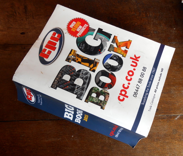
CPC’s very aptly-named Big Book
Which means that all the new devices are available to us, but we’ve lost the ability to keep on top of them. We’ve become information rich, but knowledge poor. Printed catalogs still exist, but the sheer volume of information they contain forces brevity upon their entries and expands the size of the publication to the point at which it becomes an unwieldy work of reference. We therefore tend to stick with the devices and components we know, regardless of their cost or of whether they have been superseded, and our work is poorer for it.
We need to relearn the skill of inquisitiveness when it comes to the parts we use, and to rediscover the joy of just browsing, even if the medium is now a huge suppliers’ web site rather than a paper catalog. Otherwise we’ll still be looking at circuit diagrams containing 74LS logic and 40673 MOSFETs in the 2030s, and that can’t be a good thing!
There is of course also a slightly macabre alternative scenario. The highest online price we found for 40673s was over $30 each, so if a producer can make that kind of silly money then there’s a danger that RCA’s successors will see a business model in exhuming the corpse and re-animating it, thus ensuring that we’ll never be free of the undead. We need to make sure that doesn’t happen!