2025 One-Hertz Challenge: The Flip Disc Clock

Do you like buses, or do you just like the flippy-flappy displays they use to show route information? Either way, you’ll probably love the flip-disc clock created by [David Plass].

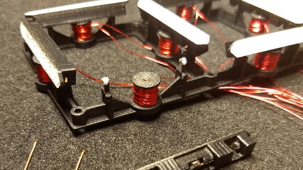
The build is based around four seven-segment flip disc displays. The modules in question are from Flipo.io. They use a hefty 0.5 amp pulse to create a magnetic field strong enough to flip the discs from one side to the other with coils placed underneath the fluro/black flipdots themselves. The modules are controlled by a Wemos D1, which uses Wi-Fi to query a NTP server to keep accurate time. It then drives the necessary segments to display the current time. The whole thing is assembled in what appears to be some kind of kitchen storage tub.

Notably, the clock flips a couple dots once every second to meet the requirements of our One-Hertz Challenge. This also makes it obvious that the clock is working when it would otherwise be static. However, [David] notes commenting out that part of the code at times, as it can be quite loud!

This clock has got fluro dots, it’s well-executed, and it’s a fine entry to the 2025 One-Hertz Challenge. We’ve also previously explored how these beautiful displays work in detail, too. Meanwhile, if you’re busy repurposing some other kind of mechanical display technology, don’t hesitate to let us know!


A Close Look At How Flip-Dot Displays Really Work

[Mike Harrison] has an upcoming project which will combine a large number of flip-dot displays salvaged from buses. [Mike] thought he knew how these things worked, and had a prototype PCB made right away. But while the PCB was being manufactured, he started digging deeper into the flip-dot’s flipping mechanism.

As he dismantled one of the flip-dots, he realized there was a lot going on under the hood than he realized. The dots are bistable — staying put when power is removed. This is achieved with a U-shaped electromagnet. The polarity of a driving pulse applied to the coil determines which way to flip the dot and saturates the electromagnet’s core in the process. Thus saturated, each dot is held in the desired position because the black side of the dot is made from magnetic material. But wait, there’s more — on further inspection, [Mike] discovered another permanent magnet mounted in the base. He’s not certain, but thinks its job is to speed up the flipping action.

Besides curiosity, the reason [Mike] is studying these so closely is that he wants to build a different driver circuit to have better and faster control. He sets out to better understand the pulse waveform requirements by instrumenting a flip-dot and varying the pulse width and voltage. He determines you can get away with about 500 us pulses at 24 V, or 1 ms at 12 V, much better that the 10 ms he originally assumed. These waveforms result in about 60 to 70 ms flip times. We especially enjoyed the slow-motion video comparing the flip at different voltages at 16:55 in the video after the break.

[Mike] still has to come up with the optimum driving circuit. He has tentatively has settled on a WD6208 driver chip from LCSC for $0.04/ea. Next he will determine the optimum technique to scale this up, deciding whether going for individual pixel control or a multiple sub-array blocks. There are mechanical issues, as well. He’s going to have to saw off the top and bottom margin of each panel. Reluctant to unsolder the 8500+ joints on each panel, his current idea is to solder new controller boards directly onto the back of the existing panels.

This video is a must-watch if you’re working on drivers for your flip-dot display project, and we eagerly look forward to any future updates from [Mike]. We also wrote about a project that repurposed similar panels a couple of years ago. There are a few details that [Mike] hasn’t figured out, so if you know more about how these flip-dots work, let us know in the comments below.

Continue reading “A Close Look At How Flip-Dot Displays Really Work”

Flip dot display submerged in oil

Giving Flip Dots The Oil Treatment To Shut Them Up

Flip dot displays are awesome — too bad it’s so hard to find large panels to play around with, but that’s for another article. [Pierre Muth] has been working to find different and interesting things to do with these flip dots, and he recently explored how you can flip them very very gently.

Now you likely remember [Pierre’s] work from earlier this year where he was pushing the speed of the displays as high as possible. Using a capacitor discharge trick he made it to 30 fps, which absolutely stunning work. This time around he attempted to do something equally impressive by micro-stepping the dots. It’s a bonkers idea and unfortunately didn’t work. It seems the dots are engineered for two steady states and you just can’t get very good performance with the in-between states.

However, along the way he had an a-ha moment. Part of what he wanted to do with the microstepping was to slow down the change of the state and for that, he just grabbed a viscous fluid that’s thicker than air: Vaseline oil. (We’d imagine it’s not the cocoa-scented variety, but who knows?) He’s taken a page out of the mineral-oil-cooled PC sub-genre and applied it to flipdots. But watch the video after the break and you’ll see that the slower animations are super pleasing to watch, and the clickity-clackity that was driving you nuts while trying to works is now whisper quiet. It’s a new dawn for displays.

Continue reading “Giving Flip Dots The Oil Treatment To Shut Them Up”

Mechanically Multiplexed Flip-Dot

Flip dots displays are timeless classics, but driving the large ones can quickly turn into a major challenge. The electromagnets require a lot of current to operate, and the driver circuits can get quite expensive. [James Bruton] wanted to build his own, but followed a bit of a different route, building a mechanically multiplexed flip dot (ball?) display.

Each of the dots on [James]’ 5×3 proof of concept is a bistable mechanical mechanism that can either show or hide a ping pong ball sized half sphere. Instead of using electromagnets, the dots are flipped by a row of micro servos mounted on a moving carriage behind the display. The mechanism is derived from one of [James]’ previous projects, a mechanical multiplexer. Each dot mechanism has a hook at the back of the mechanism for a servo to push or pull to flip the dot. A major disadvantage of this design is the fact that the servo horn must match the state of the dot before moving through the hook, otherwise it can crash and break something, which also reduces the speed at which the carriage can move.

This build was just to get a feel for the concept, and [James] already has several ideas for changes and improvements. The hook design can certainly change, and a belt drive would really speed things up. We think this mechanical display is a very interesting design challenge, and we are interested to hear how our readers would tackle it? Let us know in the comments below.

Recently we covered a 3D printed flip dot display for the first time. It’s still small and [Larry Builds] is working out the kinks, but we would love to see it eventually match the mesmerising effect of Breakfast’s large installations.

3D Printed Flip Dots

Displays have come a long way in the last few decades, but none can deliver the mesmerizing visual and audio experience of a large flip dot display. Both old panels and new panels can be expensive and difficult to source, so [Larry Builds] made his own flip dots with the help of 3D printing.

Flip dots are driven by a pair of electromagnetic posts that attract or repel a magnet embedded in the dot, and [Larry Builds] version is no different. For the electromagnets, he used M3 threaded rod with enamel wire wound around them using a drill. At first, he used a large magnet in the center of the 3D printed dot, but the magnetic field was large and strong enough to flip the surrounding dots in an array. He then changed the design to a small 4 mm diameter magnet in the edge that aligns directly with the electromagnets. This design looks very similar to those used by Breakfast for their massive installations. By modifying electromagnets and adding spacers around the magnets, he was able to reduce the operating current from 2 A to below 500 mA. [Larry Builds] also breadboarded a basic driver circuit consisting of H-bridges multiplexed to rows and columns with diodes.

We will be keeping a close eye on this project, and we look forward to seeing it evolve further. It’s definitely on our “things to build” list. We’ve embedded multiple videos after the break showing the progress thus far.

We’ve covered several interesting flip dot projects, including a water level indicator that doesn’t use any electronics and another that is crocheted. Continue reading “3D Printed Flip Dots”

30 FPS Flip-Dot Display Uses Cool Capacitor Trick

Most people find two problems when it comes to flip-dot displays: where to buy them and how to drive them. If you’re [Pierre Muth] you level up and add the challenge of driving them fast enough to rival non-mechanical displays like LCDs. It was a success, resulting in a novel and fast way of controlling flip-dot displays.

Gorgeous stackup of the completed display. [Pierre] says soldering the 2500 components kept him sane during lockdown.
If you’re lucky, you can get a used flip-dot panel decommissioned from an old bus destination panel, or perhaps the arrivals/departures board at a train station. But it is possible to buy brand new 1×7 pixel strips which is what [Pierre] has done. These come without any kind of driving hardware; just the magnetized dots with coils that can be energized to change the state.

The problem comes in needing to reverse the polarity of the coil to achieve both set and unset states. Here [Pierre] has a very interesting idea: instead of working out a way to change the connections of the coils between source and sink, he’s using a capacitor on one side that can be driven high or low to flip the dot.

Using this technique, charging the capacitor will give enough kick to flip the dot on the display. The same will happen when discharged (flipping the dot back), with the added benefit of not using additional power since the capacitor is already charged from setting the pixel. A circuit board was designed with CMOS to control each capacitor. A PCB is mounted to the back of a 7-pixel strip, creating modules that are formed into a larger display using SPI to cascade data from one to the next. The result, as you can see after the break, does a fantastic job of playing Bad Apple on the 24×14 matrix. If you have visions of one of these on your own desk, the design files and source code are available. Buying the pixels for a display this size is surprisingly affordable at about 100 €.

We’re a bit jealous of all the fun displays [Pierre] has been working on. He previously built a 384 neon bulb display that he was showing off last Autumn.

Continue reading “30 FPS Flip-Dot Display Uses Cool Capacitor Trick”

Electromagnetic 7-Segment Display Easy On The Eyes AND The Ears

We love electromagnetic displays: take the modern look of a digital readout, combine with the low-tech coil mechanism that you theoretically could create yourself, add a dash of random clacking sounds, and what’s not to like? Evidently, [Nicolas Kruse] shares our affection for these displays, because he’s taken it beyond theory and created a 7-segment magnetically-actuated display from scratch.

The display is 3D-printed, as you would expect these days. Each segment contains a small neodymium magnet, and each coil a 1 mm iron core for flux concentration. The coils are driven with a 1.6 A peak current, causing the segments to flip in less than 10 ms. [Nicolas] provides STL files for the display base, segments, and spools so you can print your own display. He’s also released the schematics and code for the driver, which uses an ATtiny44 to drive the coils through N- and P-channel MOSFETs. Initially designed to drive a passive 4×7 matrix of displays, the driver couldn’t quite manage to flip one segment without affecting its neighbors. However, for a single display, the driver works fine. We hope he figures out the matrix issue soon, because we really want to see a clock made with these displays.

You can see (and hear) a short video of the display in action after the break. The clacking does not disappoint!

Continue reading “Electromagnetic 7-Segment Display Easy On The Eyes AND The Ears”