FPGA Soft CPU Is Superscalar

We will admit it: mostly when we see a homebrew CPU design on an FPGA, it is a simple design that wouldn’t raise any eyebrows in the 1970s or 1980s. Not so with [Henry Wong’s] design, though. His x86-like design does superscalar out-of-order execution, just like big commercial modern CPUs. Of course [Henry] designs CPU architectures for Intel, so that’s not surprising. You can see a very detailed talk on the design in the video, below. You can also read the entire thesis project.

[Henry] starts out with a description of FPGAs and soft processors. He also covers the use of multiple instruction issue to increase the virtual clock rate of a CPU. In other words, if a 100 MHz CPU can do one instruction at a time, it won’t be any faster — in theory — than a 50 MHz CPU that can do two instructions at once. Of course, trying to do two at once has some overhead, so that won’t be completely true.

Continue reading “FPGA Soft CPU Is Superscalar”

A Modular Logic Analyzer For FPGAs

When working on a project, it’s incredibly helpful to be able to visualize the various signals in play. This is important when attempting to determine if what is supposed to be happening is actually happening. However, logic analyzers can be expensive, so a group from [Bruce Land]’s ECE5760 class developed their own hardware solution instead.

The primary idea behind the project is modularity. The basic building blocks of the logic analyser are coded in Verilog. They’re designed so that the number of channels and added functions can be mixed and match to suit the given purpose and the capabilities of the target FPGA platform. The team’s logic analyzer is also capable of decoding SPI and I2C in hardware, and has a graphical user interface running on an attached laptop for visualizing signals.

It’s a tidy build, and an excellent project to learn the fundamentals of both FPGA programming and the various communications protocols involved. [Bruce Land]’s classes are a hotbed of FPGA projects, from pokerbots to NES chiptune emulators. Video after the break.

Continue reading “A Modular Logic Analyzer For FPGAs”

A Stylish Pair Of FPGA Earrings

Sometimes, rather than going the commercialistic route, it can be nice to make a gift for that personal touch. [Mahesh Venkitachalam] had been down this very road before, often stumbling over that common hurdle of getting in too deep and missing the deadline of the occasion entirely. Not eager to repeat the mistake, help was enlisted early, and the iCE bling earrings were born.

The earrings were a gift for [Mahesh]’s wife, and were made in collaboration with friends who helped out with the design. The earrings use a Lattice iCE40UP5k FPGA to control an 8×8 grid of SMD LEDs. This is all achieved without the use of shift registers, with the LEDs all being driven directly from GPIO pins. This led to several challenges, such as routing all the connections and delivering enough current to the LEDs. The final PCB is a 4-layer design, which made it much easier to get all the lines routed effectively. A buffer is used to avoid damaging the FPGA by running too many LEDs at once.

It’s a tidy build, which makes smart choices about component placement and PCB design to produce an attractive end result. LEDs naturally lend themselves to jewelry applications, and we’ve seen some great designs over the years. Video after the break.

Continue reading “A Stylish Pair Of FPGA Earrings”

PokerBot Uses FPGA For Card Calculating Horsepower

Played against humans, Poker is a game as much about reading your opponent as it is about the cards you’re dealt. That doesn’t mean there aren’t certain mathematical ways to aid your decision making based on probabilities. In this vein, a group of students from Cornell’s ECE 5760 class built a pokerbot on an FPGA.

The bot uses the principle of Monte Carlo simulation to calculate the probabilities of an individual winning a hand of Limit Texas Hold’em. Calculating the entire set of possible hands is impractical, so in a Monte Carlo simulation a sample is calculated instead. By accelerating these calculations on an FPGA, the pokerbot is able to calculate 300,000 possible hands in just 150 ms, and present a probability of winning to the human player. This same calculation method is then used to make decisions for the computer players in the game, too.

The team report that the FPGA’s processing power brought a 10x speed up compared to their C++ program running on an Intel i7-6700HQ. The strong statistical calculations help to make the computer players engaging and realistic to play against.

It’s another great example of a project from Bruce Land’s classes, which are somewhat of a hotbed of development each year. Video after the break.

Continue reading “PokerBot Uses FPGA For Card Calculating Horsepower”

What’s More Accurate Than A GPS Clock? The OpenPPS GPS Clock

Making a GPS clock is a relatively straightforward process on the face of it. Buy a GPS module for a few dollars, hook it up to a microcontroller board of your choice, pick the appropriate library and write a bit of code, et voila! A clock with time-wonk bragging rights!

Of course, your GPS clock will always tell the right time, but it won’t be really right. Your microcontroller will introduce all sorts of timing errors and jitter, so at best it’ll only be nearly right. [Rick MacDonald] has been striving to quantify and minimise these errors in his OpenPPS project, which aims to be as accurate a GPS time and frequency reference as possible.

In a very comprehensive multi-page write-up, he details his progression, through the GPS modules he used, his experience with timing jitter when he used an ESP32 alone to process their output, and then his experiments with an FPGA and then temperature-compensated oscillators. It moves from being a mere description of a GPS clock into a fascinating run-down of both GPS timing itself and the development pitfalls he encountered along the way. At the end of it all he has a GPS clock in a smart 3D-printed enclosure which he admits as yet doesn’t do anything more than tell the time, but as he points out it’s a clock with minimised jitter, delay, and drift, and it remains an ongoing project that will evolve into a full-blown time and frequency standard.

If your taste in GPS clocks is far more simple, there are plenty of projects showing how a more basic one can be produced.

Circuit-Level Game Boy: Upping Emulation Ante By Simulating Every Cycle

Usually when writing emulation software for a system like the Game Boy, one makes sure to take as many shortcuts as possible in order to reduce the resources required for the emulation. This has however the unfortunate side-effect that it reduces the overall accuracy of the emulation and with it the compatibility with games on the system.

This is the basic reasoning behind projects which seek to abandon simplistic abstractions in favor of cycle-accurate, full compatibility approaches, of which MetroBoy is probably the most extreme one. Instead of abstracting away the hardware, it instead does the emulation at the circuit level. As with such other projects, this means that the emulator requires a lot more CPU cycles to get things just right. On the bright side, one can likely still run this emulator on any modern system.

As the MetroBoy author explains, he implemented code in C++ which allowed him to construct circuits in an HDL-style manner, which should theoretically also allow him to generate a Verilog (or VHDL) softcore out of the project. As a demonstration of implementing HDL in C++ it’s decidedly interesting.

An approach like this is pretty much the exact opposite of a project like the UltraHLE (ultra high-level emulator) Nintendo 64 emulator, which used the knowledge that Nintendo 64 games are written in C as a first step to creating libraries that the code in the Nintendo 64 ROMs would call instead of the native (Nintendo) libraries. This allowed N64 games to directly run on the target system, with the graphic and system calls translated by UltraHLE into native OS calls, using the 3dfx Glide API for accelerated graphics.

While an approach like UltraHLE took allows for the most minimal use of system resources by essentially foregoing emulation completely, for retro systems like the Game Boy where games were implemented in assembly on bare hardware, using this circuit-level emulation ensures that one gets the most accurate match with the original handheld console experience.

As a word of caution to those who are now itching to try out MetroBoy, its Github site notes that it currently lacks support for game saves, uses a mixture of original Game Boy (DMG) and Game Boy Advance SP (AGS) hardware that confuses some games and has rather buggy sound support.

If playing around with software-defined Game Boy circuits isn’t enough and would like to literally look inside a real Game Boy, the X-ray image from the top of the article is something Chris over at Elektronaut pulled off several years ago.

Pano Logic FGPA Hacking Just Got Easier

When Pano Logic went out of business in 2012, their line of unique FPGA-based thin clients suddenly became a burden that IT departments didn’t want anything to do with. New and used units flooded the second-hand market, and for a while you could pick these interesting gadgets up for not much more than the cost of shipping. Thanks to considerable interest from the hacking community the prices for these boxes have climbed a bit on eBay, but they’re still a great way to get your feet wet with FPGA hacking.

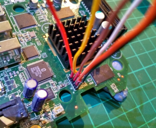
Especially now, as Pano Logic fanatic [Skip Hansen] has figured out how to flash a new firmware on them without having to crack open the case and break out the JTAG or SPI programmer. For the seasoned hardware hacker that might not seem like a big deal, but if you’re new to the game or just more interested in the software side of the equation, this trick makes things considerably more accessible. Having an external programmer is still a good idea if things go south, but if you’re just looking to flash some demos and see what the hardware is capable of this is a huge quality of life improvement.

Even if you aren’t interested in fiddling with the orphaned products of a defunct Bay Area startup, the write-up is a fascinating look at practical software reverse engineering. As it turns out, [Skip] didn’t create this new firmware update tool from scratch. He actually opened up the official Linux update utility from Pano Logic in Ghidra and was able to figure out where the firmware image actually lived inside the program. He then wrote his own tool in C which will patch the update tool with a user-supplied firmware image.

After patching, all you need to do is follow the official update procedure, which Pano Logic helpfully documented in the YouTube video after the break. [Skip] mentions he didn’t find any clear license information in the official software he was fiddling with, and of course with the company out of business it’s not too likely anyone is going to come knocking down his door anyway. Still, he says the downloads for the Pano Logic updater are still floating around on the tubes out there for you to find, so he’s not distributing anyone’s code but his own in this project.

There are a number of hackers out there working to turn the Pano Logic thin clients into useful general purpose FPGA platforms, such as [Tom Verbeure], who’s incredible graphics demos got [Skip] inspired to grab his own unit off eBay. With support for USB and SDRAM added by [Wenting Zhang] while getting his FPGA GBA emulator running on the hardware, it seems there’s never been a better time to get on the Pano Logic train.

Continue reading “Pano Logic FGPA Hacking Just Got Easier”