FPGAs are the future, and there’s a chip out there that brings us the future today. I speak, of course, of the Xilinx Zynq, a combination of a high-power ARM A9 processor and a very capable FPGA. Now the Zynq has been made Pynq with a new dev board from Digilent.
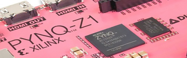
The heart of this board, is, of course, the Xilinx Zynq packing a Dual-core ARM Cortex A9 processor and an FPGA with 1.3 Million reconfigurable gates. This is a dev board, though, and with that comes memory and peripherals. To the board, Digilent added 512MB of DDR3 RAM, a microSD slot, HDMI in and out, Ethernet, USB host, and GPIOs, some of which match the standard Arduino configuration.
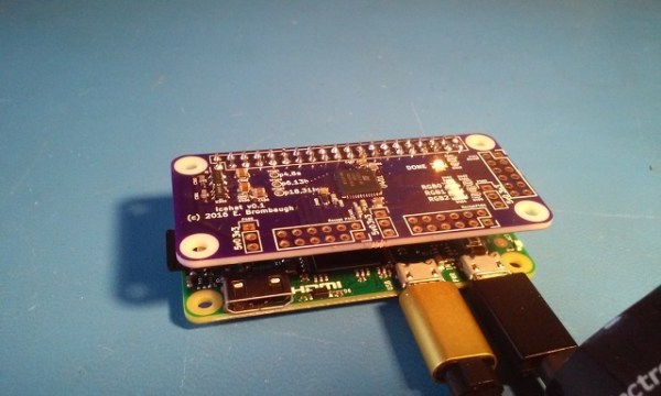
This isn’t the first Zynq board out there by any measure. Last year, [antti] had a lot of fun with the Zynq and created the ZynqBerry, a Zynq in a Raspberry Pi form factor, and a Zynq Arduino shield. Barring that, we’ve seen the Zynq in a few research projects, but not so much in a basic dev board. The Pynq Zynq is among the first that will be produced in massive quantities.
There is, of course, one downside to the Pynq Zynq, and that is the price. It’s $229 USD, or $65 with an educational discount. That’s actually not that bad for what you’re getting. FPGAs will always be more expensive than an SoC stolen from a router or cell phone, no matter how powerful it is. That said, putting a powerful ARM processor and a hefty FPGA in a single package is an interesting proposition. Adding HDMI in and out even more so. Already we’ve seen a few interesting applications of the Zynq like synthesizers, quadcopters, and all of British radio. With this new board, hopefully a few enterprising FPGA gurus will pick one up and tell the rest of us mere mortals how to do some really cool stuff.