Simple Magnetic Levitator

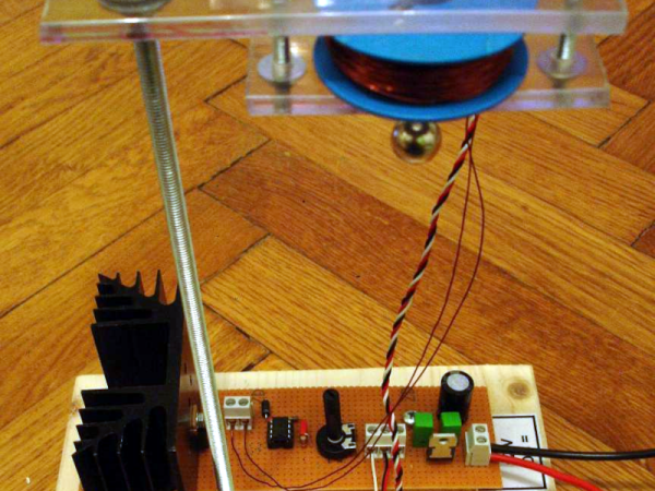
[Stoppi] always has exciting projects and, as you can see in the video below, the latest one is a very simple magnetic levitator design. The design is classic and simple: a 5 V regulator IC, a Hall effect sensor, a 741 op amp, and a MOSFET to turn the electromagnet on and off.

Sure, there are a few passive components and a diode, too, but nothing exotic. The sensor normally presents 2.5 V of output. The voltage rises or drops depending on the polarity of the magnetic field. The stronger the field, the more the voltage changes away from the 2.5 V center.

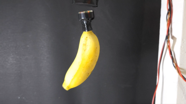
The op amp acts as a comparator with a potentiometer setting the trip point. As the ball moves up towards the coil, the voltage increases, triggering the comparator, which turns off the FET. With no current through the coil, there’s no more electromagnet, and the ball starts to fall.

Of course, as the ball falls, the voltage from the sensor also drops, and this eventually turns on the electromagnet. The ball eventually reaches a relatively stable position.

This is one of those cases where a simple analog circuit might work better than a digital one. Or make it hard on yourself and use an FPGA.

Continue reading “Simple Magnetic Levitator”

A shot of the underside of a "One Fast Cat" cat wheel with an installed ESP8266 and hall effect sensors attached to the base.

Spy On Your Cat To Make Sure It Gets Its Paws In

[Scott Cutler] has a young cat, [Cygnus], that loves to run on a cat wheel and [Scott] had some some important questions about [Cygnus]’s usage of the cat wheel like, how often it’s used, what direction is preferred and how fast does [Cygnus] go. To answer these questions, [Scott] put some telemetry sensors onto the cat wheel and analyzed the results.

An ESP8266 microcontroller and two 3144E hall effect modules were used to sense eight magnets glued onto the outer housing of a “One Fast Cat” cat wheel. [Scott] installed the ESP8266 and hall effect modules onto the base support for the wheels, using 3D printed brackets to secure them.

For the software side, the ESP8266 attaches an interrupt handler whenever a sensor passes by, recording a window of three previous measurements for valid sample determination and, if accepted, uses the time between samples to infer direction and speed. The ESP8266 connects to a pre-configured local WiFi network and has a telnet interface to extract stored log information, in the form of JSON data.

[Scott] has some nice graphs and other data visualizations on [Cygnus]’s usage, including a preference for running at 3 AM, achieving a maximum speed of 14 mph and an average of 4 seconds per run. The source is available on GitHub and the STL files are available embedded in [Scott]’s write-up. We’ve featured cat exercise trackers before with a giant hamster wheel outfitted with a Raspberry Pi and it’s nice to see some options that allow for a retrofit option in addition to a complete DIY solution.

A man sits in front of a wooden table. There is a black box with a number of knobs hand-labeled on blue painter's tape. A white breadboard with a number of wires protruding from it is visible on the box's left side. An oscilliscope is behind the black box and has a yellow waveform displaying on its screen.

A More Expressive Synth Via Flexure

Synthesizers can make some great music, but sometimes they feel a bit robotic in comparison to their analog counterparts. [Sound Werkshop] built a “minimum viable” expressive synth to overcome this challenge. (YouTube)

Dubbed “The Wiggler,” [Sound Werkshop]’s expressive synth centers on the idea of using a flexure as a means to control vibrato and volume. Side-to-side and vertical movement of the flexure is detected with a pair of linear hall effect sensors that feed into the Daisy Seed microcontroller to modify the patch.

The build itself is a large 3D printed base with room for the flexure and a couple of breadboards for prototyping the circuits. The keys are capacitive touch pads, and everything is currently held in place with hot glue. [Sound Werkshop] goes into detail in the video (below the break) on what the various knobs and switches do with an emphasis on how it was designed for ease of use.

If you want to learn more about flexures, be sure to checkout this Open Source Flexure Construction Kit.

Continue reading “A More Expressive Synth Via Flexure”

Levitating Banana Is An Excellent Conversation Starter

“I really like your floating banana.” If that’s something you’ve always wanted your guests to say when visiting your living room, this levitating banana project from [ElectroBing] is for you.

The design is simple. It relies on a electromagnet to lift the banana into the air. As bananas aren’t usually ferromagnetic, a simple bar magnet is fitted to the banana to allow it to be attracted to the electromagnet. One could insert the magnets more stealthily inside the banana, though this would come with the risk that someone may accidentally consume them, which can be deadly.

Of course, typically, the magnet would either be too weak to lift the banana, or so strong that it simply attracted the banana until it made contact. To get the non-contact levitating effect, some circuitry is required. A hall effect sensor is installed directly under the electromagnet. As the banana’s magnet gets closer to the electromagnet, the hall effect sensor’s output voltage goes down. Once it drops below a certain threshold, a control circuit cuts power to the electromagnet. As the banana falls away, power is restored, pulling the banana back up. By carefully controlling the power to the electromagnet on a continuous basis, the banana can be made to float a short distance away in mid-air.

It’s a fun build, and one that teaches many useful lessons in both physics and electronics. Other levitation techniques exist, too, such as through the use of ultrasound. Video after the break.

Continue reading “Levitating Banana Is An Excellent Conversation Starter”

A composite picture with a 3D printed cylinder with a magnet at one end held in a 3D printed housing ring on the left composite picture and a fridge buzzer board with buzzer, CR2032 battery, MCP430 microcontroller and hall effect sensor slid into a 3D printed base on the right part of the composite picture

Don’t Lose Your Cool With This Fridge Buzzer

[CarrotIndustries] wanted to add an audible warning for when the refrigerator door was left open. The result is a fridge buzzer that attaches to the inside of a fridge door and starts buzzing if the door is left ajar for too long.

The main components of the fridge buzzer consist of an MSP430G2232 low-power MCU connected to a SI7201 hall sensor switch, along with a CR2032 battery holder, push button and buzzer. The MSP430’s sleep mode is used here, consuming less than 3 µA of current which [CarrotIndustries] estimates lasting 9 years on a 235 mAh CR2032 battery.

A 3D printed housing is created so that the board slides into a flat bed, which can then be glued onto to the fridge door. The other mechanical component consists of a cylinder with a slot dug out for a magnet, where the cylinder sits in a mounting ring that’s affixed to the side of the fridge wall that the end of the door closes on. The cylinder can be finely positioned so that when the refrigerator is closed, the magnet sits right over the hall sensor of the board, allowing for sensitivity that can detect even a partial close of the fridge door.

All source code is available on [CarrotIndustries] GitHub page, including the Horizon EDA schematics and board files, the Solvespace mechanical files, and source code for the MSP430. We’ve featured an IoT fridge alarm in the past but [CarrotIndustries]’ addition is a nice, self contained, alternative.

Tracing In 2D And 3D With Hall Effect Sensors

Pantographs were once used as simple mechanical devices for a range of tasks, including duplicating simple line drawings. [Tim] decided to make a modern electronic version that spits out G-Code instead.

The design relies on a 3D-printed pantograph assembly, mounted upon a board as a base. A pair of Hall effect sensors are mounted in the pantograph, which, along with a series of neodymium magnets, can be used to measure the angles of the pantograph’s joints. The Hall sensors are read by an Arduino Nano, which computes the angles into movement of the pantograph head and records it as G-Code. This can simply be displayed on the attached LCD display, or offloaded to a computer for storage.

[Tim] explains the basic theory behind the work in an earlier piece, where he built a set of electronic dividers using the same techniques. He didn’t stop there, either. He also built a more complex version that works in 3D that he calls it the Electronic Point Mapper, which can be used to generate point clouds with a 3D-capable pantograph mechanism.

It’s a neat way to learn about geometry, and could even be useful if you’re doing some work in tracing 2D drawings or measuring 3D objects.

Continue reading “Tracing In 2D And 3D With Hall Effect Sensors”

3D Printed Maglev Switches Are So Hot Right Now

It doesn’t happen all the time, but over the years we’ve noticed that once we feature a project, a number of very similar builds often find themselves in our tip line before too long. Of course, these aren’t copycats; not enough time has passed for some competitive maker to spin up their own version. No, most of the time it’s somebody else who was working on a very similar project in isolation, and who now for the first time realizes they aren’t alone.

Thanks to this phenomenon we’re happy to report that yet another 3D printable magnetic levitation switch has come to light. Developed by [famichu], this take on the concept is markedly different from what we’ve seen previously, which in a way makes the whole thing even more impressive. It’s one thing for multiple hackers to develop similar projects independently of each other, as the end goal often dictates the nature of the design itself. But here we’re seeing a project that took the same core concepts and ran in a different direction. Continue reading “3D Printed Maglev Switches Are So Hot Right Now”