A common complaint about open hardware and software is that the aesthetic aspects of the projects often leave something to be desired. This isn’t wholly surprising, as the type of hackers who are building these things tend to be more concerned with how well they work than what they look like. But there’s certainly nothing wrong with putting a little polish on a well designed system, especially if you want “normal” people to get excited about it.
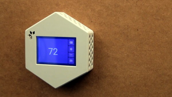
 For a perfect example, look no further than the HestiaPi Touch. This entry into the 2019 Hackaday Prize promises to deliver all the home automation advantages of something like Google’s Nest “smart” thermostat without running the risk of your data being sold to the highest bidder. But even if we take our tinfoil hat out of the equation, it’s a very slick piece of hardware from a functional and visual standpoint.
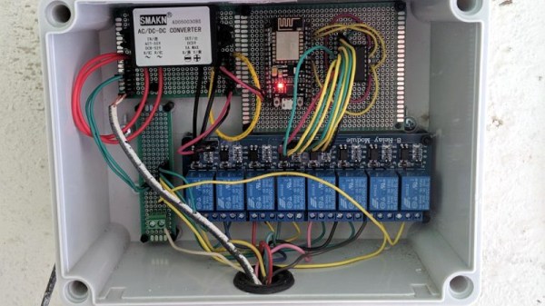
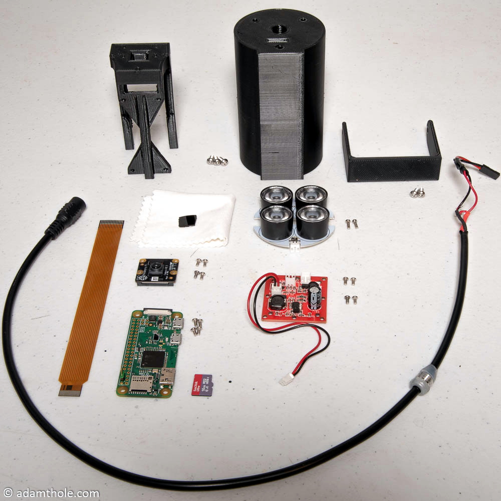
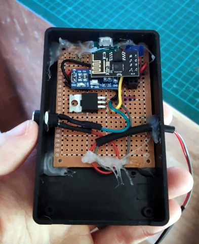
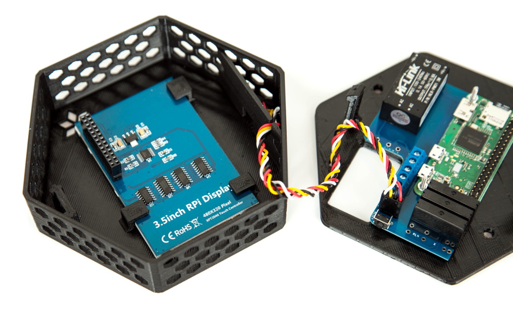
As you probably guessed from the name, the thermostat is powered by the Raspberry Pi Zero, which is connected to a custom PCB that includes a couple of relays and a connector for a BME280 environmental sensor. The clever design of the 3D printed case means that the 3.5 inch touch screen LCD on the front can connect directly to the Pi’s GPIO header when everything is buttoned up.
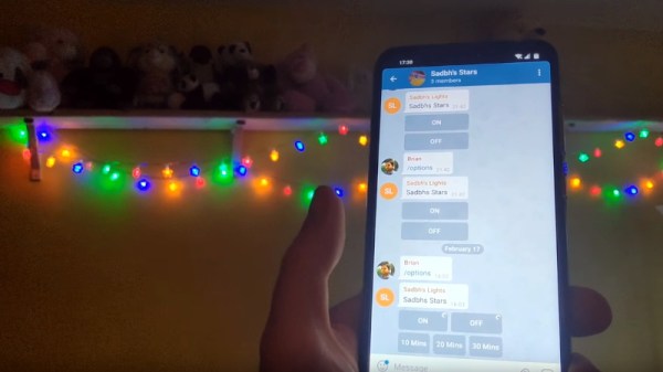
Of course, the hardware is only half the equation. To get the HestiaPi Touch talking to all the other smart gadgets in your life, it leverages the wildly popular OpenHAB platform. As demonstrated in the video after the break, this allows you to use the HestiaPi and its mobile companion application to not only control your home’s heating and air conditioning systems, but pretty much anything else you can think of.
The HestiaPi Touch has already blown past its funding goal on Crowd Supply, and the team is hard at work refining the hardware and software elements of the product; including looking at ways to utilize the unique honeycomb shape of the 3D printed enclosure to link it to other add-on modules.
Continue reading “HestiaPi: A Stylish Open Hardware Thermostat”