[Igor] has an AS5600 magnetic rotary encoder chip on a breakout board. Normally, you’d think that was an easy device to work with since it has an I2C interface. But [Igor] wanted to do it the hard way. What’s the hard way? By hand. He directly manipulates the clock and data lines using some push buttons. You can see how it goes in the video below.
This is possible because the controlling device — in this case [Igor] — gets to set the clock rate, and there’s no reason it has to be regular. We have to admit that it never occurred to us to do this, but we have written “bit banged” I2C-like code before.
It was probably a reasonable assumption that the “Tiny” in our recently concluded Tiny Games Contest mostly referred to the physical footprint of the game. And indeed, that’s the way most of the entries broke, which resulted in some pretty amazing efforts. [Anders Nielsen], however, took the challenge another way and managed to stuff a seagull-centric side-scroller into just 500 bytes of code.
That’s not to say that the size of [Anders]’s game is physically huge either. Flappy Larus, as he calls his game, runs on his popular 65uino platform, a 6502 microcontroller in the familiar Arduino Uno form factor. So it’s pretty small to begin with, and doesn’t even need any additional components other than the tiny OLED screen which has become more or less standard for the 65uino at this point. The only real add-on is a piezo speaker module, which when hooked up to the I2C data line happens to make reasonable approximations of a squawking seagull, all without adding a single byte of code. Check out a little game play in the video below.
Last time, I gave you an overview of what you get from I2C, basics like addressing, interface speeds, and a breakdown of pullups. Today, let’s continue looking into I2C capabilities and requirements – level shifting, transfer types, and quirks like combined transfers or clock stretching.
Remember when dead batteries were something you’d just toss in the trash? Those days are long gone, thankfully, and rechargeable battery packs have put powerful cordless tools in the palms of our hands. But when those battery packs go bad, replacing them becomes an expensive proposition. And that’s a great excuse to pop a pack open and see what’s happening inside.
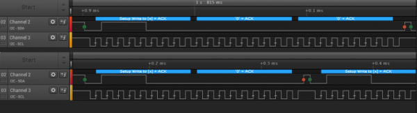
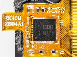
The battery pack in question found its way to [Don]’s bench by blinking some error codes and refusing to charge. Popping it open, he found a surprisingly packed PCB on top of the lithium cells, presumably the battery management system judging by the part numbers on some of the chips. There are a lot of test points along with some tempting headers, including one that gave up some serial data when the battery’s test button was pressed. The data isn’t encrypted, but it is somewhat cryptic, and didn’t give [Don] much help. Moving on to the test points, [Don] was able to measure the voltage of each battery in the series string. He also identified test pads that disable individual cells, at least judging by the serial output, which could be diagnostically interesting. [Don]’s reverse engineering work is now focused on the charge controller chip, which he’s looking at through its I2C port. He seems to have done quite a bit of work capturing output and trying to square it with the chip’s datasheet, but he’s having trouble decoding it.
This would be a great place for the Hackaday community to pitch in so he can perhaps get this battery unbricked. We have to admit feeling a wee bit responsible for this, since [Don] reports that it was our article on reverse engineering a cheap security camera that inspired him to dig into this, so we’d love to get him some help.
Cats are notorious for interrupting workflow. Whether it’s in the kitchen, the garden, or the computer, any feline companion around has a way of getting into mischief in an oftentimes disruptive way. [Robin] has two cats, and while they like to sit on his desk, they have a tendency to interrupt his mouse movements while he’s using his Apple trackpad. Rather than solve the impossible problem of preventing cats from accessing areas they shouldn’t, he set about building a customized tiny trackpad that integrates with his keyboard and minimizes the chance of cat interaction.
The keyboard [Robin] uses is a split ergonomic keyboard. While some keyboards like this might use a standard USB connection to join the two halves, the ZSA Voyager uses I2C instead and even breaks the I2C bus out with a pogo pin-compatible connector. [Robin] originally designed a 3D-printed integrated prototype based on a Cirque trackpad that would clip onto the right side of the keyboard and connect at this point using pogo pins, but after realizing that the pogo pin design would be too difficult for other DIYers to recreate eventually settled on tapping into the I2C bus on the keyboard’s connecting cable. This particular keyboard uses a TRRS connector to join the two halves, so getting access to I2C at this point was as simple as adding a splitter and plugging in the trackpad.
With this prototype finished, [Robin] has a small trackpad that seamlessly attaches to his ergonomic keyboard, communicates over a standard protocol, and avoids any unwanted cat-mouse action. There’s also a build guide if you have the same keyboard and want to try out this build. He does note that using a trackpad this small involves a bit of a learning curve and a larger-than-average amount of configuration, but after he got over those two speed bumps he hasn’t had any problems. If trackpads aren’t your style, though, with some effort you can put a TrackPoint style mouse in your custom mechanical keyboard instead.
In the previous two HID articles, we talked about stealing HID descriptors, learned about a number of cool tools you can use for HID hacking on Linux, and created a touchscreen device. This time, let’s talk about an underappreciated HID standard, but one that you might be using right now as you’re reading this article – I2C-HID, or HID over I2C.
HID as a protocol can be tunneled over many different channels. If you’ve used a Bluetooth keyboard, for instance, you’ve used tunneled HID. For about ten years now, I2C-HID has been heavily present in laptop space, it was initially used in touchpads, later in touchscreens, and now also in sensor hubs. Yes, you can expose sensor data over HID, and if you have a clamshell (foldable) laptop, that’s how the rotation-determining accelerometer exposes its data to your OS.
This capacitive touchscreen controller is not I2C-HID, even though it is I2C. By [Raymond Spekking], CC-BY-SA 4.0Not every I2C-connected input device is I2C-HID. For instance, if you’ve seen older tablets with I2C-connected touchscreens, don’t get your hopes up, as they likely don’t use HID – it’s just a complex-ish I2C device, with enough proprietary registers and commands to drive you crazy even if your logic analysis skills are on point. I2C-HID is nowhere near that, and it’s also way better than PS/2 we used before – an x86-only interface with limited capabilities, already almost extinct from even x86 boards, and further threatened in this increasingly RISCy world. I2C-HID is low-power, especially compared to USB, as capable as HID goes, compatible with existing HID software, and ubiquitous enough that you surely already have an I2C port available on your SBC.
In modern world of input devices, I2C-HID is spreading, and the coolest thing is that it’s standardized. The standardization means a lot of great things for us hackers. For one, unlike all of those I2C touchscreen controllers, HID-I2C devices are easier to reuse; as much as information on them might be lacking at the moment, that’s what we’re combating right now as we speak! If you are using a recent laptop, the touchpad is most likely I2C-HID. Today, let’s take a look at converting one of those touchpads to USB HID.
I had one of those why-didn’t-I-think-of-it moments this week, reading this article about multiplexing I2C on the ESP32 microcontroller. The idea is so good, and so simple, that it’s almost silly that it’s not standard hacker practice. And above all, it actually helps solve a problem that I’ve got. This is why I read Hackaday every day.
I2C is great in that it lets you connect up multiple devices to a pair of wires using a very bus architecture. Every device has its own address, the host calls them out, and hopefully all other devices keep quiet while just the right one responds. But what happens when you want to use a few of the same sensors, where each IC has the same address? The usual solution is to buy a multiplexer chip.
But many modern microcontrollers, like the ESP32, have an internal multiplexer setup that lets you map the pins with the dedicated hardware peripherals, usually at initialization time. Indeed, I’ve been doing it as an “init” task so long, I never thought to do it otherwise. But that’s exactly the idea behind [BastelBaus]’s hack – if you dynamically reassign the pins, you can do the I2C multiplexing with the chip you’ve got. This should probably work for any other chips that have multiple assignable pins for hardware peripherals as well.
Cool idea, but really simple. Why hadn’t I ever thought of it? I think it’s because I’ve always had this init / mainloop schema in my mind, which for instance the Arduino inherited and formalized in its setup() and loop() functions. Pin mappings go in the init section, right?
So what this hack really amounts to, for me, is a rethinking of what’s static and what’s dynamic. It’s always worth questioning your assumptions, especially when you’re facing a problem that requires a creative solution. Sometimes limitations are only in your mind. Have you had your mind opened recently by a tiny little hack?
This article is part of the Hackaday.com newsletter, delivered every seven days for each of the last 200+ weeks. It also includes our favorite articles from the last seven days that you can see on the web version of the newsletter.
Want this type of article to hit your inbox every Friday morning? You should sign up!