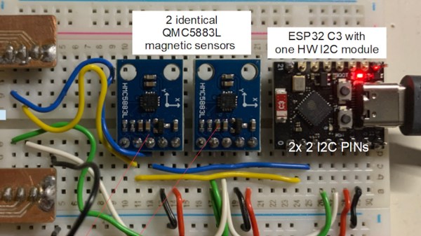
Hands On: Bus Pirate 5

If you’ve been involved with electronics and hardware hacking for awhile, there’s an excellent chance you’ve heard of the Bus Pirate. First introduced on the pages of Hackaday back in 2008 by creator Ian Lesnet, the open hardware multi-tool was designed not only as away to easily tap into a wide array of communication protocols, but to provide various functions that would be useful during hardware development or reverse engineering. The Bus Pirate could talk to your I2C and SPI devices, while also being able to measure frequencies, check voltages, program chips, and even function as a logic analyzer or oscilloscope.

Bus Pirate 3, circa 2012

The Bus Pirate provided an incredible number of tools at a hobbyist-friendly price, and it wasn’t long before the device became so popular that it achieved a milestone which only a few hardware hacking gadgets can boast: its sales started to get undercut by cheap overseas clones. Of course, as an open hardware device, this wasn’t really a problem. If other companies wanted to crank out cheap Bus Pirates, that’s fine. It freed Ian up to research a next-generation version of the device.

But it turns out that was easier said than done. It’s around this point that the Bus Pirate enters what might be considered its Duke Nukem Forever phase. It took 15 years to release the sequel to 1996’s Duke Nukem 3D because the state-of-the-art in video games kept changing, and the developers didn’t want to be behind the curve. Similarly, Ian and his team spent years developing and redeveloping versions of the Bus Pirate that utilized different hardware platforms, such as the STM32 and ICE40 FPGA. But each time, there would be problems sourcing components, or something newer and more interesting would be released.

But then in 2021 the Raspberry Pi Pico hit the scene, and soon after, the bare RP2040 chip. Not only were the vast I/O capabilities of the new microcontroller a perfect fit for the Bus Pirate, but the chip was cheap and widely available. Finally, after years of false starts, the Bus Pirate 5 was born.

I was able to grab one of the first all-new Bus Pirates off the production line in January, and have been spending the last week or so playing around with it. While there’s definitely room for improvement on the software side of things, the hardware is extremely promising, and I’m very excited to be see how this new chapter in the Bus Pirate story plays out.

Continue reading “Hands On: Bus Pirate 5”

Flash Programmer Shows Some Nifty Tricks

A handy tool to have on the bench is a Flash chip programmer, and the ones based around the CH341A USB bus converter chip are readily available. But the chip is capable of so much more than simply programming nonvolatile memory, so [Tomasz Ostrowski] has created a utility program that expands its capabilities. The software provides easy access to a range of common i2c peripherals. He’s got it talking to smart batteries, GPIOs, environmental sensors, an OLED display, and even an FM radio module. The code can all be found in a GitHub repository. The software is Windows-only so no fun and games for Linux users yet — but since it’s open source, new features are just a pull request away.

The CH341A is much more than an i2C controller, it also supports a surprising range of other interfaces including SPI, UARTs, and even a bidirectional parallel printer port. Maybe this software will serve to fire the imagination of a few others, and who knows, we could see more extended use of this versatile chip. Oddly we’ve featured these programmer boards before, though in a tricky flashing job.

Flip The Switch On This I2C Controlled USB Hub

You’ve probably seen USB hubs with physical switches for each port, they provide a handy way to cut the power to individual devices, but only if you’re close enough to flip them. They won’t do you much good if you want to pull the plug on a USB gadget remotely.

That’s why [Jim Heaney] created the I2C-USB-Hub. The device takes your standard USB 2.0 hub circuit, and adds in a MT9700 P-MOSFET load switch for each port. The enable pin on each of these switches is in turn connected to one of the output pins of a PCA9557PW I2C I/O chip. That means controlling each port is as easy as sending the proper sequence of bits over the wire, though [Jim] says he does plan on writing up an Arduino library to make flipping the digital switches a little more user friendly.

Since the 8-bit chip had a few extra pins left over, [Jim] wired one up to serve as a master control for the LED indicator lights on the PCB. Another is used to adjust the current limit on the MT9700 between 500 mA and 1 A.

While naturally we’re big fans of spinning up your own hardware here at Hackaday, we’ve also seen similar results achieved by modifying an off-the-shelf USB hub.

A Usable Arduino Debugging Tool

For as popular as the Arduino platform is, it’s not without its problems. Among those is the fact that most practical debugging is often done by placing various print statements throughout the code and watching for them in the serial monitor. There’s not really a great way of placing breakpoints or stepping through code, either. But this project, known as eye2see, hopes to change that by using the i2c bus found in most Arduinos to provide a more robust set of debugging tools.

The eye2see software is set up to run on an Arduino or other compatible microcontroller, called the “probe”, which is connected to the i2c bus on another Arduino whose code needs to be debugged. Code running on this Arduino, which is part of the eye2see library, allows it to send debugging information to the eye2see probe. With a screen, the probe can act as a much more powerful debugger than would otherwise typically be available, being able to keep track of variables in the main program, setting up breakpoints, and outputting various messages on its screen.

The tool is not without its downsides, though. The library that needs to run on the host Arduino slows down the original program significantly. But for more complex programs, the tradeoff with powerful debugging tools may be worth it until these pieces of code can be removed and the program allowed to run unencumbered. If you’d like to skip needing to use a second Arduino, we’ve seen some other tools available for debugging Arduino code that can run straight from a connected PC instead.

Four jumper wires with white heatshrink on them, labelled VCC, SCL, SDA and GND

Three Pitfalls In I2C Everyone Wishes Weren’t There

The best part of I2C is that it is a bus that is available just about anywhere, covering a vast ecosystem of devices that offer it as a hardware-defined interface, while being uncomplicated enough that it can also be implemented purely in software on plain GPIO pins. Despite this popularity, I2C is one of those famous informal standards that feature a couple of popular implementations, while leaving many of the details such as exact timing, bus capacitance and other tedious details to the poor sod doing the product development. Thus it is that we end up with articles such as a recent one on the tongue-twisting [pair of pared pears] blog, covering issues found while implementing an I2C slave.

As with any shared bus, whether multi-master or not, figuring out when the bus is clear is a fun topic, yet one which can cause endless headaches. One issue here comes from a feature that the SMBus version of I2C calls quick read/write. This allows for the rapid transfer of some data. Still, depending on the data returned by the slave, it may appear to the master that nothing is happening yet, since SDA is being held low by the slave until the stop condition, essentially locking the bus.

I2C hold times example.

Where things get even more exciting comes generally in the form of what logic analyzers love to traumatically call a ‘spurious start/stop condition’. This refers to the behavior of SDA and SCL, with SDA going low before SCL indicating an error. This can occur due to a hold time that’s too low, causing other devices on the bus to miss the transition. Here SMBus defines a transition time of 300 ns, while I2C calls for 0 seconds, but it’s now suggested to delay calling a start/stop condition until a delay of 300 ns has passed. Essentially, it would seem that implementing a hold time is the way forward until evidence to the contrary appears.

The third pitfall pertains to the higher-speed modes of I2C, including Fast-Mode (FM) and Fast-Mode Plus (FM+). Backward compatibility with these higher speed versions is absent to spotty. Although FM+ (introduced by NXP in 2007) is supposed to be backward compatible with slower speeds, effectively the timing requirement differences between the FM+ and FM standards are too large to compensate for. At least in the current versions of the standards, but one of the joys of I2C is that there’s always another new set of revisions to look forward to.

A Simple Guide To Bit Banged I2C On The 6502

We covered [Anders Nielsen]’s 65duino project a short while ago, and now he’s back with an update video showing some more details of bit-banging I2C using plain old 6502 assembly language.

Obviously, with such a simple system, there is no dedicated I2C interface hardware, so the programmer must take care of all the details of the I2C protocol in software, bit-banging it out to the peripheral and reading back the response one bit at a time.

The first detail to concern us will be the I2C addresses of the devices being connected to the bus and how low-level bit manipulation is used to turn the 7-bit I2C address into the byte being bit-banged. As [Anders] shows, setting a bit is simply a logical-OR operation, and resetting a bit is a simple logical-AND operation using the inversion (or one’s complement) bit to reset to form a bitmask. As many will already know, this process is necessary to code for a read or a write I2C operation. A further detail is that I2C uses an open-collector connection scheme, which means that no device on the bus may drive the bus to logical high; instead, they must release the drive by going to the high impedance state, and an external pull-up resistor will pull the bus high. The 6532 RIOT chip (used for I/O on the 65unio) does not have tristate control but instead uses a data direction register (DDR) to allow a pin to be an input. This will do the job just fine, albeit with slightly odd-looking code, until you know what’s going on.

From there, it’s a straightforward matter to write subroutines that generate the I2C start, stop, and NACK conditions that are required to write to the SSD1306-based OLED to get it to do something we can observe. From these basic roots, through higher-level subroutines, a complete OLED library in assembly can be constructed. We shall sit tight and await where [Anders] goes next with this!

We see I2C-connected things all the time, like this neat ATtiny85-based I2C peripheral, and whilst we’re talking about the SSD1306 OLED display controller, here’s a hack that shows just how much you can push your luck with the I2C spec and get some crazy frame rates.

Continue reading “A Simple Guide To Bit Banged I2C On The 6502”

Interlaken Want To Connect All The Chips

One of the problems with designing things on a chip is finding a good way to talk to the outside world. You may not design chips yourself, but you care because you want to connect your circuits — including other chips — to the chips in question. While I2C and SPI are common solutions, today’s circuits are looking for more bandwidth and higher speeds, and that’s where Interlaken comes in. [Comcores] has an interesting post on the technology that blends the best of SPI 4.2 and XAUI.

The interface is serial, as you might expect. It can provide both high-bandwidth and low-latency multi-channel communications. Interlaken was developed by Cisco and Cortina Systems in 2006 and has since been adopted by other industry-leading companies. Its latest generation supports speeds as high as 1.2 Tbps.

Continue reading “Interlaken Want To Connect All The Chips”