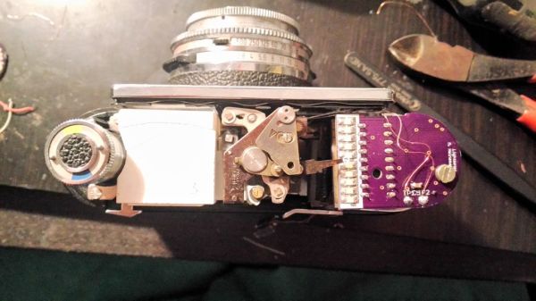
The black blob IC is of a particular annoyance to the modern hacker. There is no harm in peeking under the hood to see how the IC works. But when it’s covered in a mountain of seemingly indestructible epoxy, this can be a bit difficult. And such was the case for [Jamie], who had found an old electronic pocket dictionary whose main PC board boasted not one, but two of the black blob ICs.
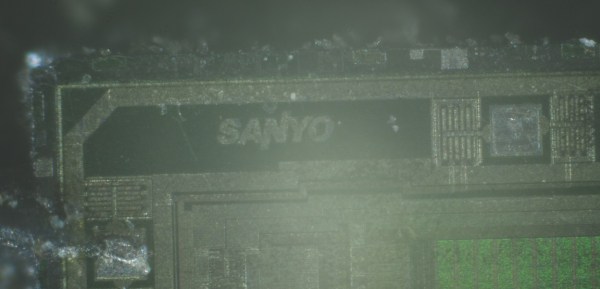
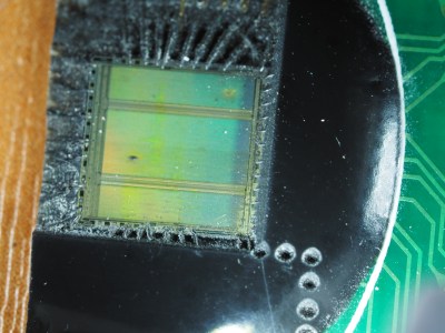 The lack of traces between the two pushed [Jamie’s] curiosity past the tipping point. He didn’t have access to any nitric acid which is used in the customary chemical decapping process. He did, however, have access to a laser cutter. It turns out that decapping ICs with a laser cutter is not only possible, it’s not that difficult.
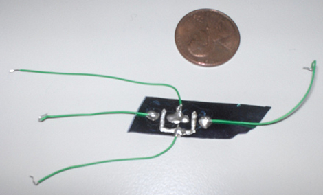
100% power at 300mm per seconds on a cheap 40 Watt “eBay” laser cutter is all it takes. Three passes did the trick for [Jamie], but this will be dependent on the thickness of the black blob epoxy. Each case will likely be unique.
Got a laser cutter? Then take a peek at a few black blob ICs and let us know what you find.
Thanks to [ex-parrot] for the tip!