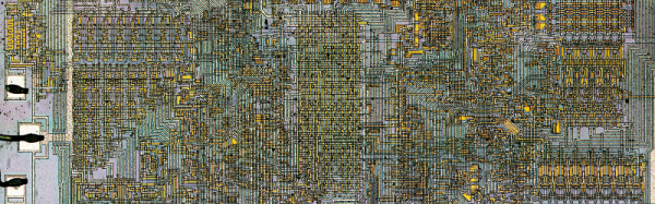
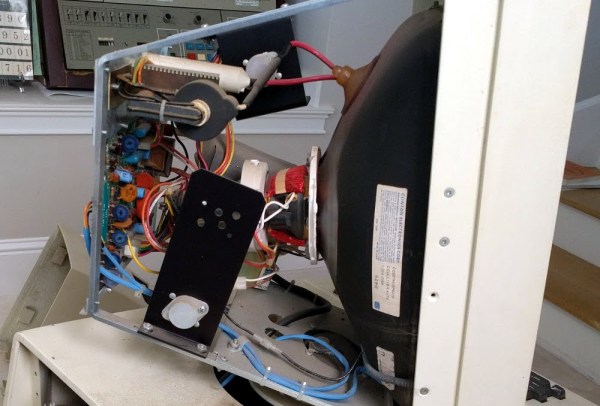
Lately, [Ken Shirriff] has been on some of the most incredible hardware adventures. In his most recent undertaking we find [Ken] elbow-deep in the core memory of a 50-year-old machine, the IBM 1401. The computer wasn’t shut down before mains power was cut, and it has refused to boot ever since. The culprit is in the core memory support circuitry, and thanks to [Ken’s] wonderful storytelling we can travel along with him to repair an IBM 1401.
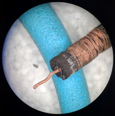
From a hardware standpoint core memory makes us giddy. It’s a grid of wires with ferrite toroids at every intersection. Bits can be set or cleared based on how electricity is applied to the intersecting wires. [Al Williams] walked through some of the core memory history last year and we enjoyed hearing [Pamela Liou] recount the story of how textile workers consulted on the fabrication of core memory for the Apollo missions during her OHWS Talk in October. But giddiness aside, core memory has pretty much gone the way of the dodo having been displaced by technologies that take up exponentially less space.
We chuckle at [Ken’s] mention of the core memory capacity for the IBM 1401. It has 4000 characters of memory built-in (with another 12,000 in an expansion box) and he goes on to detail that these are 6-bit characters on a machine that operates in decimal and not binary (hence 4k instead of the base-2 friendly 4096).
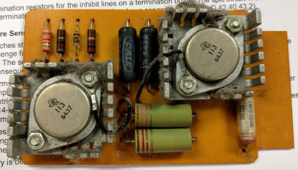
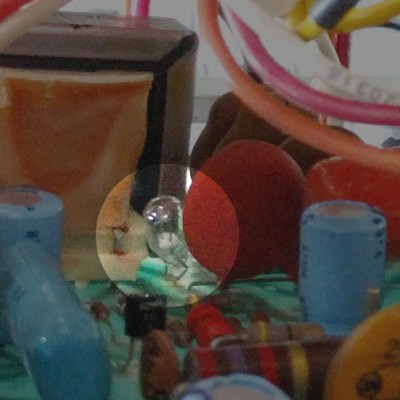
You may remember his work a few years back to repair core memory on the same model. The Museum has two 1401’s, which turned out to be a huge help in trouble-shooting this. After tracing out the control lines, the repair team began swapping cards between the working and non-working machines. They were able to bring it back online — establishing one of the green inductors was bad — only to be struck with a second fault in the power supply.
Get this, [Ken] comments that “the whole computer is pre-silicon”. When working through the PSU, some suspect transistors were replaced with germanium power transistors. Those may have been a red-herring, as a penciled-in fuse on the original schematics turned out to be the linchpin of the PSU repair. Buried deep in the assembly, replacing the designed-to-fail part let the ancient beast awake once more.
Machines of this quality were heavily documented, and the schematics make this type of trouble-shooting a lot more manageable. But it’s still as much an art as it is skill. Make sure to give [Ken’s] article a read, and look around at the other repair jobs he’s documented — keeping these machines in service is becoming wizard-level work and we love being able to follow along.
 On paper, a light bulb lights up when you put current through it. In real life, it is a bit more complicated. An incandescent filament starts off as almost a dead short and draws a lot of current for a very brief time. As the current flows, the filament gets hot and the resistance goes up. That reduces the current draw. This effect — known as inrush current — is the scourge of designers trying to turn on light bulbs with transistors or other electronic switches.
 We have most recently seen [Ken] at work