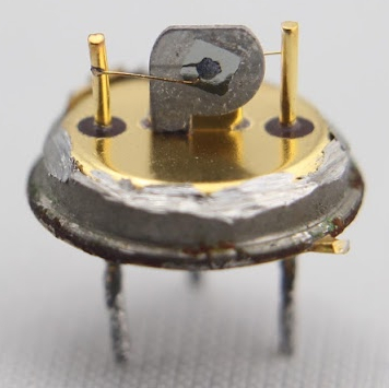
We always look forward to a new blog post by [Ken Shirriff] and this latest one didn’t cure us of that. His topic this time? Comparing two Game Boy audio chips. People have noticed before that the Game Boy Color sounds very different than a classic Game Boy, and he wanted to find out why. If you know his work, you won’t be surprised to find out the comparison included stripping the die out of the IC packaging.
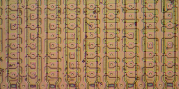
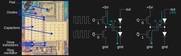
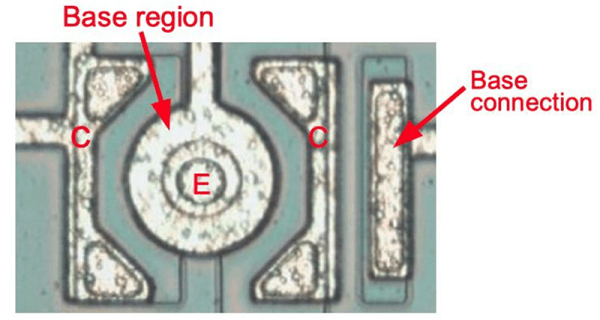
[Ken’s] explanation of how transistors, resistors, and capacitors appear on the die are helpfully illustrated with photomicrographs. He points out how resistors are notoriously hard to build accurately on a production IC. Many differences can affect the absolute value, so designs try not to count on exact values or, if they do, resort to things like laser trimming or other tricks.
Capacitors, however, are different. The exact value of a capacitor may be hard to guess beforehand, but the ratio of two or more capacitor values on the same chip will be very precise. This is because the dielectric — the oxide layer of the chip — will be very uniform and the photographic process controls the planar area of the capacitor plates with great precision.
We’ve decapsulated chips before, and we have to say that if you are just starting to look at chips at the die level, these big chips with bipolar transistors are much easier to deal with than the fine and dense geometries you’d find even in something like a CPU from the 1980s.
We always enjoy checking in with [Ken]. Sometime’s he’s taking apart nuclear missiles. Sometimes he is repairing an old computer. But it is always interesting.
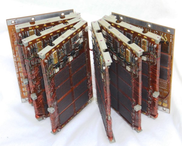
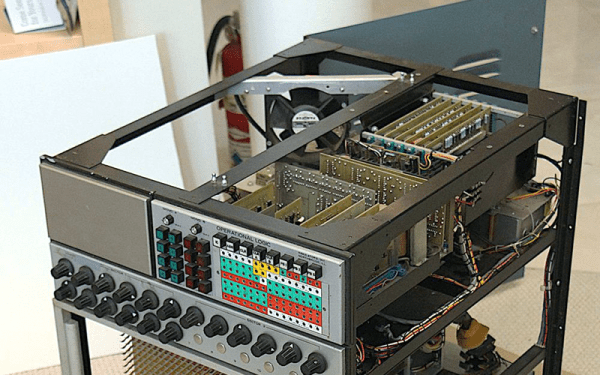
 Amazingly these computers were composed of all digital logic, no centralized controller chip in this baby. That explains the need for the seven circuit boards which host a legion of logic chips, all slotting into a backplane.