We love close-up pictures of intricate work, and [w] hits the spot with a tiny joule thief in a fuse case (social media post, embedded below) powered by an old coin cell from a watch. It’s so tiny!
Ethernet transformers contain tiny coils.
A joule thief is a sort of minimum-component voltage booster that can suck nearly every last drop of energy from even seemingly-drained batteries, and is probably most famously used to light LEDs from cells that are considered “dead”.
Many joule thief designs feature hand-wound coils, which is great for junk box builds but certainly becomes more of a challenge for a tiny build like this one.
We really like that [w] salvaged a miniscule coil from an Ethernet transformer, most of which look like blocky SMD components from the outside but actually contain tiny coils.
The joule thief has been the basis of plenty of hacks over the years, and it’s always nice to see new twists on the concept.
[mitxela] has a tiny problem, literally: some of his projects are so small as to defy easy programming. While most of us would probably solve the problem of having no physical space on a board to mount a connector with WiFi or Bluetooth, he took a different path and gave this clever light-based programming interface a go.
For initial experiments he wisely chose his larger but still diminutive LED matrix badge, which sports a CH32V003 microcontroller, an 8×8 array of SMD LEDs, and not much else. The video below is a brief summary of the effort, while the link above provides a much more detailed account of the proceedings, which involved a couple of false starts and a lot of prototyping that eventually led to dividing the matrix in two and ganging all the LEDs in each half into separate sensors. This allows [mitxela] to connect each side of the array to the two inputs of an op-amp built into the CH32V003, making a differential sensor that’s less prone to interference from room light. A smartphone app alternately flashes two rectangles on and off with the matrix lying directly on the screen to send data to the badge — at a low bitrate, to be sure, but it’s more than enough to program the badge in a reasonable amount of time.
We find this to be an extremely clever way to leverage what’s already available and make a project even better than it was. Here’s hoping it spurs new and even smaller LED projects in the future.
LEDs are a wonderful technology. You put in a little bit of power, and you get out a wonderful amount of light. They’re efficient, cheap, and plentiful. We use them for so much!
What you might not have known is that these humble components have a secret feature, one largely undocumented in the datasheets. You can use an LED as a light source, sure, but did you know you can use one as a sensor?
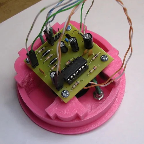
Picture it: you’re on the treadmill, running through a forest, sweating like a pig, and the doorbell rings because a package is being delivered. Would you even hear it? Chances are, if you’re rocking out to music on headphones and your treadmill is as noisy as [Antonio]’s, you wouldn’t, and you’d once again face the dreaded ‘we’ll try later’ slip.
The first 555 is wired up in astable mode to control the tempo of the flashing light, and the second timer is in monostable mode to control the length of time the light flashes. Power comes from the doorbell’s 9V, which is wired up through an existing Ethernet jack.
Now whenever the doorbell rings, [Antonio] has 60 seconds of flashing light in order to react, stop the treadmill, and jump off to answer the door. To conserve power when [Antonio] is relaxing, there’s an on/off switch.
In a lot of ways, Etch-A-Sketch is the perfect toy; simple, easy to use, creative, endlessly engaging, and as a bonus, it’s completely mechanical. We find that last attribute to be a big part of its charm, but that’s not to say an electronic version of the classic toy can’t be pretty cool, especially when it’s done without the aid of a microcontroller.
This is one of those “because I can” projects that we always find so interesting, and more so because it wasn’t entirely clear to [BigZaphod] that he had the skills to pull it off. While his initial design centered around a bunch of 8×8 LED matrix displays and a 256×4-bit RAM chip, the rest of it was a lot of hand-waving. After a few experiments with addressing the LEDs, [Zaphod] started filling in the blanks with a refresh circuit using a 555 — naturally — and a pair of counters. Properly debounced encoders for the horizontal and vertical controls came next, along with more counters to track the cursor and a host of other circuits that ended up looking like a “one of each” selection from the 7400-series catalog.
While we do wish for a schematic on this one, it’s still a pretty enjoyable video, and the end product seems to work really well. The electronic version has a few features the original lacks, such as wrapping the cursor to the other side of the screen. We’d imagine that the buttons on the encoders could be put to work, too; perhaps a click could make it so you can move the cursor without leaving a trail behind. That might be a challenge to execute in logic, but then again, that was the point of the whole thing.
Still jonesing for that mechanical Etch-A-Sketch experience? Not a problem.
Unless you’re living in a bicycle paradise like the Netherlands, most people will choose to add some sort of illumination to their bicycle to help drivers take note that there’s something other than a car using the road. Generally, simple flashing LEDs for both the front and the rear is a pretty good start, but it doesn’t hurt to add a few more lights to the bicycle or increase their brightness. On the other hand, if you want to add some style to your bicycle lighting system then this persistence of vision (POV) display called the BikeBeamer from [locxter] might be just the thing.
The display uses four LED strips, each housed in their own 3D printed case which are installed at 90-degree angles from one another in between the spokes of a standard bicycle wheel. An ESP32 sits at the base of one of the strips and is responsible for storing the image and directing the four displays. This is a little more complex than a standard POV display as it’s also capable of keeping up with the changing rotational speeds of the bicycle wheels when in use. The design also incorporates batteries so that no wires need to route from the bike frame to the spinning wheels.
This is an ongoing project for [locxter] as well, meaning that there are some planned upgrades even to this model that should be in the pipe for the future. Improving the efficiency of the code will hopefully allow for more complex images and even animations to be displayed in the future, and there are also some plans to improve the PCB as well with all surface-mount components. There are a few other ways to upgrade your bike’s lighting as well, and we could recommend this heads-up headlight display to get started.
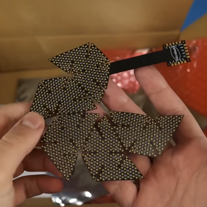
[Carl Bugeja] finds the engineering behind the Las Vegas Sphere fascinating, and made a video all about the experience of designing and building a micro-sized desktop version. [Carl]’s version is about the size of a baseball and crams nearly a thousand RGB pixels across the surface.
A four-layer flexible PCB is the key to routing data and power to so many LEDs.
Putting that many addressable LEDs — even tiny 1 mm x 1 mm ones — across a rounded surface isn’t exactly trivial. [Carl]’s favored approach ended up relying on a flexible four-layer PCB and using clever design and math to lay out an unusual panel shape which covers a small 3D printed geodesic dome.
Much easier said that done, by the way. All kinds of things can and do go wrong, from an un-fixable short in the first version to adhesive and durability issues in later prototypes. In the end, however, it’s a success. Powered over USB-C, his mini “sphere” can display a variety of patterns and reactive emojis.
As elegant and impressive as the engineering is in this dense little display, [Carl] has some mixed feelings about the results. 945 individual pixels on such a small object is a lot, but it also ends up being fairly low-resolution in the end. It isn’t very good at displaying sharp lines or borders, so any familiar shapes (like circles or eyes) come out kind of ragged. It’s also expensive. The tiny LEDs may be only about 5 cents each, but when one needs nearly a thousand of them for one prototype that adds up quickly. The whole bill of materials comes out to roughly $250 USD after adding up the components, PCB, controller, and mechanical parts. It’s certainly a wildly different build than its distant cousin, the RGB cube.
Still, it’s an awfully slick little build. [Carl] doubts there’s much value in pursuing the idea further, but there are plenty of great images and clips from the build. Check out the video, embedded below.