Hacking A Non-Dimmable LED Fixture

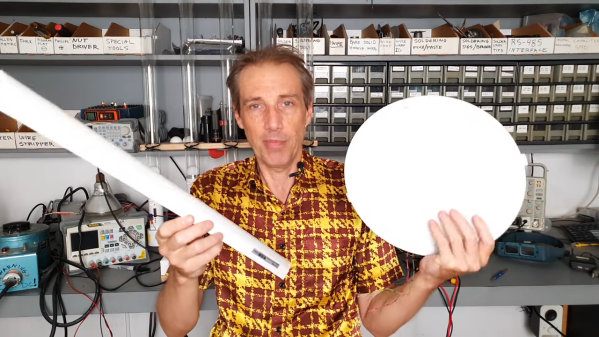
For most of us, the solution to having a non-dimmable LED light bulb but needing a dimmable one is a simple as a drive to the store to get the right kind of bulb. But that seems downright boring, not to mention wasteful, so when [Leo Fernekes] was faced with this problem, he looked for a way to make a non-dimmable bulb dimmable.

To be fair, there was a financial aspect to this hack, too. [Leo] had a bunch of cheap non-dimmable light fixtures he wanted to put to use. He started with a teardown and reverse-engineering of a light strip, which contains little more than LEDs and a small buck converter. His analysis of the circuit led him to a solution for dimming the light: inserting a MOSFET as a shunt around the LEDs. That and the addition of a diode to isolate the LEDs from the current regulator would allow for simple PWM-control of the lights via a microcontroller.

As is typical with these things, there were complications. [Leo] found that a timing problem resulted in flickering LEDs; the fix came from adding a sync circuit that cleverly leveraged a flip-flop inside the PIC16 microcontroller he chose for the circuit. His prototype incorporates these modifications, plus an interface that supports the DALI protocol for architectural lighting control. As always, [Leo] is quick to point out that mixing line voltage into your projects is not without risks, which he takes pains to mitigate. And as is also typical for his projects, [Leo] gives just the right amount of detail to understand the theory behind his design.
Continue reading “Hacking A Non-Dimmable LED Fixture”

AOI By DIY

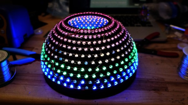
As anyone who has ever assembled a run of PCBs will tell you, quality inspection of solder joints can be a difficult process. Even under a microscope their appearances can be deceptive, and one silver blob can be perfect while its neighbour conceals a problem. The electronics industry have developed inspection tools to help, including optical inspection devices. It’s one of these that [Sina Roughani] has built, in the form of a hemispherical 3D printed dome with concentric rings of coloured LEDs mounted within it.

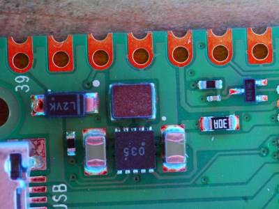
The principle behind this tool is as unexpected and simple as it is clever; by having different colours of light from different elevations of the dome it ensures that each different angle of the solder joint surface reflects a different colour. Thus a colour photograph shot from directly above the board allows visual inspection of the quality of the solder joints by the rainbow of colours that appears around their edges. This process can even be automated with OpenCV or similar, hence the process is referred to as Automated Optical Inspection, or AOI.
The technique is demonstrated with some pictures of a Raspberry Pi Pico, on which it shows really well the rainbow-edged solder joints and the red colour reflected from flat pads. What at first might seem like a novelty lighting effect becomes a very useful inspection tool.

PCB inspection is a subject we’ve covered before, though perhaps we don’t all have access to X-rays.

A Modern Homage To The TIL311 Display

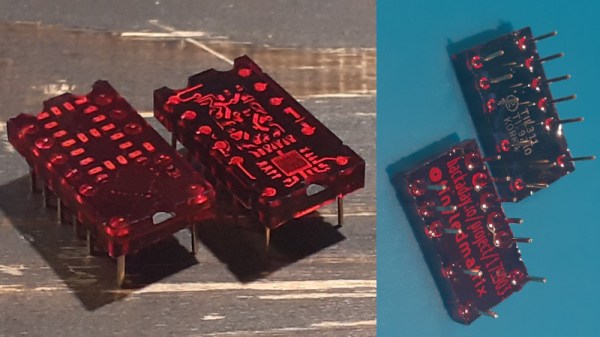
Back in the 1970s, there were a huge variety of esoteric LED displays on the market. One of those was the DIP-packaged TIL311 from Texas Instruments, capable of displaying hexadecimal, from 0-9 and A-F. While these aren’t readily available anymore, the deep red plastic packages had some beauty to them, so [Alex] set about making a modern recreation.

The build consists of a small PCB fitted with 20 LEDs, and a STM8S microcontroller to run the show. This can be used to emulate the original decoder logic on the TIL311, or programmed with other firmware in order to test the display or enable other display functions. Where the project really shines however is in the visual presentation. [Alex] has been experimenting with potting the hardware in translucent red resin to properly emulate the look of the original parts, which goes a long way to getting that cool 70s aesthetic. Attention to detail is top notch, with [Alex] going so far as to carefully select pins that most closely match the square-cut design on the original TIL311 part.

It’s a fun build that could be useful for a project when you can’t get working new old stock. We’ve seen similar efforts for Nixie tubes in the past. Video after the break.

Continue reading “A Modern Homage To The TIL311 Display”

Linear Pong Loses A Dimension But Remains Challenging

When Pong hit the scene in the early 70s, there was something about the simplicity of the 2D monochrome tennis game that made it engaging enough that enthusiastic proto-gamers shorted-out machines by stuffing their coin boxes to overflowing.  But even with the simplicity of Pong’s 2D gameplay, the question becomes: could it by made simpler and still be playable?

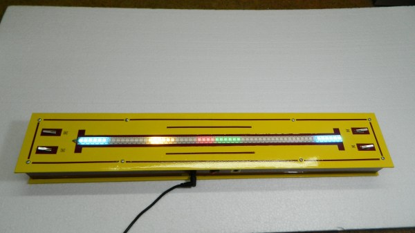
Surprisingly, if this one-dimensional Pong game is any indication, it actually seems like it can. Where the original Pong made you line up your paddle with the incoming ball, with the main variable being the angle of the carom from your opponent, [mircemk]’s version, limited to a linear game field, makes the ball’s speed the variable. Players take control of the game with a pair of buttons at the far ends of a 60-LED strip of WS2812s. The ball travels back and forth along the strip, bouncing off a player’s paddle only if they push their button at the exact moment the ball arrives. Each reflection back to the opponent occurs at a random speed, making it hard to get into a rhythm. To add some variety, each player has a “Boost” button to put a little spice on their shot, and score is kept by LEDs in the center of the play field. Video of the game play plus build info is below the break.

With just a Neopixel strip, an Arduino Nano, and a small handful of common parts, it should be easy enough to whip up your own copy of this surprisingly engaging game. But if the 2D-version is still more your speed, maybe you should check out the story of its inventor, [Ted Dabney]. Or, perhaps building a clock that plays Pong with itself to idle the days away is more your speed.

Continue reading “Linear Pong Loses A Dimension But Remains Challenging”

LEDs From Dubai: The Royal Lights You Can’t Buy

[Clive] had an interesting video about LED lights from Philips. You can’t buy them unless you live in Dubai. Apparently inspired by the ruler of Dubai, Sheikh Mohammad Bin Rashid Al Maktoum, who wanted more efficient and longer-lasting bulbs. The secret? A normal LED bulb uses an LED “filament” at 1 watt each. The Dubai bulbs run at about a fourth of that which means they need more LEDs to get the same amount of light, but they should last longer and operate more efficiently.

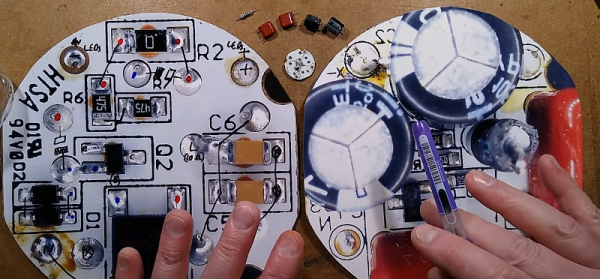
After exploring the brightness and color of different lamps, [Clive] tears one up and finds some surprises inside. The LEDs get over 200V each and the driver circuit has a lot of pairs of components, possibly to keep the size small for the high voltages involved, although it could be to improve reliability, [Clive] wasn’t sure.

By reducing the power, [Clive] was able to count that each LED strip contains 21 LEDs. He also notes some of the oddities in construction that appear to be for reliability and ease of manufacturing. We aren’t sure how that compares to the construction of conventional bulbs. The circuit includes a bridge rectifier and a linear current regulator using a MOSFET.

The bulbs cost a bit more, but if you factor in the probable long life, their total cost over time should be reasonable. Overall, it is interesting that a nice design came from what amounts to government regulation. Of course, there is a price: in exchange for the development of the bulbs, Philips has the exclusive right to make and sell the bulbs for the next several years. They expect to sell 10 million lamps by the end of 2021, although they are only available, currently, in Dubai.

Continue reading “LEDs From Dubai: The Royal Lights You Can’t Buy”

Dynamic Map Of Italy On A PCB

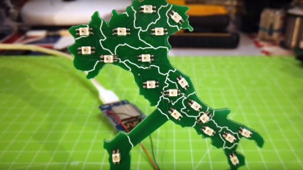
While most PCBs stick to tried-and-true methods of passing electrons through their layers of carefully-etched copper, modern construction methods allow for a large degree of customization of most aspects of these boards. From solder mask to number of layers, and even the shape of the board itself, everything is open for artistic license and experimentation now. [Luca] shows off some of these features with his PCB which acts as a live map of Italy.

The PCB is cut out in the shape of the famous boot, with an LED strategically placed in each of 20 regions in the country. This turns the PCB into a map with the RGB LEDs having the ability to be programmed to show any data that one might want. It’s powered by a Wemos D1 Mini (based on an ESP8266) which makes programming it straightforward. [Luca] has some sample programs which fetch live data from various sources, with it currently gathering daily COVID infection rates reported for each of the 20 regions.

The ability to turn a seemingly boring way to easily attach electronic parts together into a work of art without needing too much specialized equipment is a fantastic development in PCBs. We’ve seen them turned into full-color art installations with all the mask colors available, too, so the possibilities for interesting-looking (as well as interesting-behaving) circuits are really opening up.

Continue reading “Dynamic Map Of Italy On A PCB”

Smart Power Delivery For Long LED Strips

Addressable LED strips, most commonly using the WS2812B, have revolutionized the pursuit of the glowiest and flashiest of builds. No longer does a maker have to compromise on full RGB color or number of LEDs due to the limitations of their chosen microcontroller, or fuss around with multiplexing schemes. However, the long strips of bright LEDs do have an issue with voltage drop on long runs, leading to dimming and color irregularities. Thankfully, [Jan Mrázek] has come up with a useful solution in the form of the Neopixel Booster.

The device consists of a small PCB which packs a 5 volt regulator capable of putting out up to 4 amps. It’s designed with pads that match typical Neopixel strips, such that it can be neatly soldered in every 50cm or every 60 LEDs or so. Each booster PCB is fed with a set of fat power wires, at between 6-18 volts. This allows electricity to be fed to the full length of the strip at higher voltage, and thus lower current, greatly reducing resistive power losses. By having several regulators along the length of the strip, it helps guarantee that the whole length of a long run is receiving plenty of voltage and current and can light up the correct color as desired.

It’s a well thought out solution to a frustrating problem, and [Jan’s] efforts on the design front mean that a 5 meter long waterproof strip can be converted in around about an hour. We can imagine this could be manufactured into strips in future, too. If you’re wondering what to do with all those LEDs, consider making yourself a custom display.