Whenever [MakerMan] hits our tip line with one of his creations, we know it’s going to be something special. His projects are almost exclusively built using scrap and salvaged components, and really serve as a reminder of what’s possible if you’re willing to open your mind a bit. Whether done out of thrift or necessity, he proves the old adage that one man’s trash is often another’s treasure.
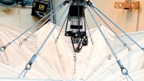
 We’ve come to expect mainly practical builds from [MakerMan], so the beautiful ceiling light which he refers to as a “Kinetic Chandelier”, is something of a change of pace. The computer controlled light is able to fold itself up like an umbrella while delivering a pleasing diffuse LED glow. He tells us it’s a prototype he’s building on commission for a client, and we’re going to go out on a limb and say he’s going to have a very satisfied customer with this one.
Like all of his builds, the Kinetic Chandelier is almost entirely built out of repurposed components. The support rods are rusty and bent when he found them, but after cutting them down to size and hitting them with a coat of spray paint you’d never suspect they weren’t purpose-made. The light’s “hub” is cut out of a chunk of steel with an angle grinder, and uses bits of bike chain for a flexible linkage.
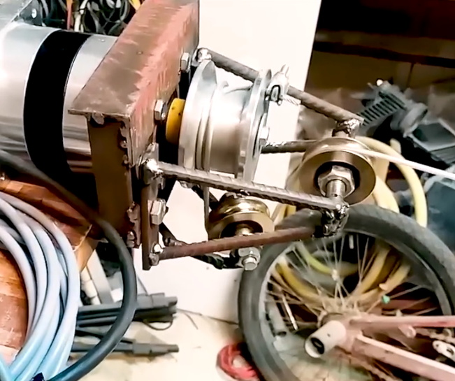
Perhaps most impressive is his DIY capstan which is used to raise and lower the center of the light. [MakerMan] turns down an aluminum pulley on a lathe to fit the beefy gear motor, and then pairs that with a few idler pulleys held in place with bits of rebar welded together. It looks like something out of Mad Max, but it gets the job done.
Finally, he salvages the LED panels out of a couple of cheap work lights and welds up some more rebar to mount them to the capstan at the appropriate angle. This gives the light an impressive internal glow without a clear source when viewed from below, and really gives it an otherworldly appearance.
This isn’t the first time we’ve seen a hacker put together their own chandelier, or even the first time we’ve seen it done with scrap parts. But what [MakerMan] has put together here may well be the most objectively attractive one we’ve seen so far.
Continue reading “Beautiful Moving Origami Light Made From Scrap”

 tiny BGA components (ok, that one might be more cool than practical). Perhaps our favorite use is to create art, and [Mohit Bhoite] is an absolute genius of the form. He’s so prolific that it’s difficult to point to a particular one of his projects as an exemplar, though he has