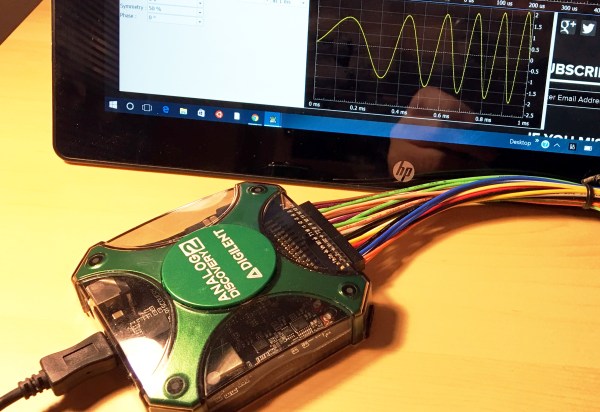
Hackaday Prize Entry: The Cheapest Logic Analyzer

There are piles of old 128MB and 256MB sticks of RAM sitting around in supply closets and in parts bins. For his Hackaday Prize project, [esot.eric] is turning these obsolete sticks of RAM into something useful – a big, fast logic analyzer. It’s cheap, and simple enough that it can be built on a breadboard.

If using old SDRAM in strange configurations seems familiar, you’re correct. This project is based on [esot.eric]’s earlier AVR logic analyzer project that used a slow AVR to measure 32 channels of logic at 30 megasamples per second. The only way this build was possible was by hacking an old stick of RAM to ‘free run’, automatically logging data to the RAM and reading it out with an AVR later.

This project expands on the earlier projects by using bigger sticks of RAM faster, with the ultimate goal being a 32-bit, 133MS/s logic analyzer that is more of a peripheral than a single, monolithic project. With a Raspberry Pi Zero, a stick of RAM, and a few miscellaneous logic chips, this project can become anything from a logic analyzer to a data logger to an oscilloscope. It’s weird, yes, but the parts to make this very handy tool can be found in any hackerspace or workshop, making it a great trick for the enterprising hardware hacker.

SDRAM Logic Analyzer Uses An AVR And A Dirty Trick

We often see “logic analyzer” projects which are little more than microcontrollers reading data as fast as they can, sending it to a PC, and then plotting the results. Depending on how fast the microcontroller is, these projects range from adequate to not very useful.

At first glance, [esot.eric’s] logic analyzer project has an AVR in it, so it ought to be on the low end of the scale. Then you look at the specs: 32 channels at 30 megasamples per second. How does that work with an AVR in it?

The answer lies in the selection of components. The analyzer uses a 128MB SDRAM DIMM (like an older PC might use for main memory). That makes sense; the Arduino can’t store much data internally. However, it isn’t the storage capacity that makes this choice critical. It seems [esot.eric] has a way to make the RAM “free run”.

The idea is to use the Arduino (or other host microcontroller) to set up the memory. Some of the memory’s output bits feedback to the address and data lines. Then the microcontroller steps aside and the SDRAM clocks samples into its memory by itself at the prevailing clock rate for the memory.

Continue reading “SDRAM Logic Analyzer Uses An AVR And A Dirty Trick”

UController Code Profiler Debugs Your Microcontroller

When working on digital circuits that operate at high frequencies it helps to have some special tools on hand. Things like oscilloscopes and logic analyzers are priceless when something isn’t working right. Another great tool would be this hardware-based profiler that [Mike] came up with while he was working on another project.

The profiler connects to USB and shows up as a serial port. Normally [Mike] used a set of LEDs to get information about how his microcontrollers work, but for this project that wasn’t enough. The uController Code Profiler can provide the main loop running time, time functions and sections of code, keep track of variables, and a few other tasks as well, all with nanosecond resolution.

The source code isn’t provided but a hex file is available, along with a schematic and an include file, if you want to try this one out on your next project. Like this homemade logic analyzer, this could be a powerful tool in your microcontroller arsenal. Simply include the file with various pieces of your code to get it up and running!

Review: DSLogic Logic Analyzer

Logic analyzers historically have been the heavy artillery in an engineer’s arsenal. For many of us, the name invokes mental images of large HP and Tektronix iron with real CRT screens. Logic connections were made through pods, with hundreds of leads weaving their way back to the test equipment. The logic analyzer came out when all else failed, when even a four channel scope wasn’t enough to figure out your problems. Setting them up was a pain – if you were lucky, the analyzer had a PC keyboard interface. If not, you were stuck typing your signal names into the front panel keyboard. Once setup though, logic analyzers were great at finding bugs. You can see things you’d never see with another tool – like a data bus slowly settling out after the read or write strobe.

There have been a number of USB based logic analyzers introduced in recent years, but they didn’t really catch on until Saleae released their “Logic” line of devices. Low cost, high-speed, and easy to use – these devices were perfect. They also inspired an army of clone devices based upon the same Cypress Semiconductor parts. DSLogic designed by DreamSource Labs, can be thought of as an open source evolution of the original Saleae device.

DSLogic appeared in 2013 as a Kickstarter campaign for an open source logic analyzer with an optional oscilloscope extension. I think it’s safe to say that they did well, raising $111,497 USD, more than 10 times their initial goal of $10,000 USD. These days both the DSLogic and the oscilloscope extension are available at The Hackaday Store. In this review we’re focusing on the logic analyzer portion of the tool. 

Click past the break for the full story!

Continue reading “Review: DSLogic Logic Analyzer”

Hackaday Prize Entry: A BeagleBone Logic Analyzer

If you have a BeagleBone, you already have a lot of tools. We’ve seen them used in driving hundreds of LEDs at a very high frame rate, used as a video card for ancient computers, and as a software defined radio. For his entry to The Hackaday Prize, [Kumar] turned his BeagleBone into a 14-channel, 100Msps logic analyzer that’s good enough to debug just about all those hobby electronics projects you’re working on.

The BeagleBone is only able to have this sort of performance as a logic analyzer because of its PRUs, those fancy peripherals that make the Beagle great at blinking pins really, really fast. [Kumar] is using both PRUs in the BeagleBone for this project. PRU1 reads from the input probes, and PRU0 writes all the samples into DDR memory directly. From there, the samples are off to kernel modules and apps, either sigrok, dd, or something you coded up in Python.

Compared to the cheap logic analyzers we have today like the Salae Logic and the DSLogic, [Kumar]’s project is just as good as any commercial offering (provided you can live with 14 channels instead of 16), and because it’s based on a BeagleBone, the software is infinitely expandable.

UPDATE: After this post was written but before it was published, [Kumar] finished up a blog post on how he’s building a logic analyzer with the BeagleBone’s PRUs. It’s a true tutorial, with enough code demos to allow anyone to build their own 8-bit analyzer on a BeagleBone, and there are more updates coming.


The 2015 Hackaday Prize is sponsored by:

Turn Your BeagleBoneBlack In To A 14-channel, 100Msps Logic Analyzer

The BeagleBoneBlack is a SoC of choice for many hackers – and quite rightly so – given its powerful features. [abhishek] is majoring in E&E from IIT-Kharagpur, India and in 2014 applied for a project at beagleboard.org via the Google Summer of Code project (GSoC). His project, BeagleLogic aims to realize a logic analyzer using the Programmable Real-Time units on board the AM335X SoC family that powers the BeagleBone and the BeagleBone Black.

The project helps create bindings of the PRU with sigrok, and also provides a web-based front-end so that the logic analyzer can be accessed in much the same way as one would use the Cloud9 IDE on the BeagleBone/BeagleBone Black to create a new application with BoneScript.

Besides it’s obvious use as a debugging tool, the logic analyzer can also be a learning tool that can be used to understand digital signals. BeagleLogic turns the BeagleBone Black into a 14-channel, 100Msps Logic Analyzer. Once loaded, it presents itself as a character device node /dev/beaglelogic. In stand-alone mode, it can do binary captures without any special client software. And when used in conjunction with the sigrok library, BeagleLogic supports software triggers and decoding for over 30 different digital protocols.

The analyzer can sample signals from 10Hz upto 100MHz, in 8 or 16 bits and up to a maximum of 14 channels. Sample depth depends on free RAM, and upto 320MB can be reserved for BeagleLogic. There’s also a web interface, which, once installed on the BeagleBone, can be accessed from port 4000 and can be used for low-volume captures (up to 3K samples).

[abhishek] recently added the BeagleLogic Cape which can be used to debug logic circuits up to 5V safely. Source files for BeagleLogic as well as the Cape are available via his github repos. [abhishek] blogged about his project on his website where there’s a lot more information and links to be found. Catch a video of BeagleLogic after the break.

Continue reading “Turn Your BeagleBoneBlack In To A 14-channel, 100Msps Logic Analyzer”

Bathroom Scale

Reverse Engineering A Bathroom Scale For Automated Weight Tracking

[Darell] recently purchased a fancy new bathroom scale. Unlike an average bathroom scale, this one came with a wireless digital display. The user stands on the scale and the base unit transmits the weight measurement to the display using infrared signals. The idea is that you can place the display in front of your face instead of having to look down at your feet. [Darell] realized that his experience with infrared communication would likely enable him to hack this bathroom scale to automatically track his weight to a spreadsheet stored online.

[Darell] started by hooking up a 38khz infrared receiver unit to a logic analyzer. Then he recorded the one-way communication from the scale to the display. His experience told him that the scale was likely using pulse distance coding to encode the data. The scale would start each bit with a 500ms pulse. Then it would follow-up with either another 500ms pulse, or a 1000ms pulse. Each combination represented either a 1 or a 0. The problem was, [Darell] didn’t know which was which. He also wasn’t sure in which order the bits were being transmitted. He modified a software plugin for his logic analyzer to display 1’s and 0’s on top of the waveform. He then made several configurable options so he could try the various representations of the data.

Next it was time to generate some known data. He put increasing amounts of weight on the scale and recorded the resulting data along with the actual reading on the display. Then he tried various combinations of display settings until he got what appeared to be hexadecimal numbers increasing in size. Then by comparing values, he was able to determine what each of the five bytes represented. He was even able to reconstruct the checksum function used to generate the checksum byte.

Finally, [Darell] used a Raspberry Pi to hook the scale up to the cloud. He wrote a Python script to monitor an infrared receiver for the appropriate data. The script also verifies the checksum to ensure the data is not corrupted. [Darell] added a small LED light to indicate when the reading has been saved to the Google Docs spreadsheet, so he can be sure his weight is being recorded properly.