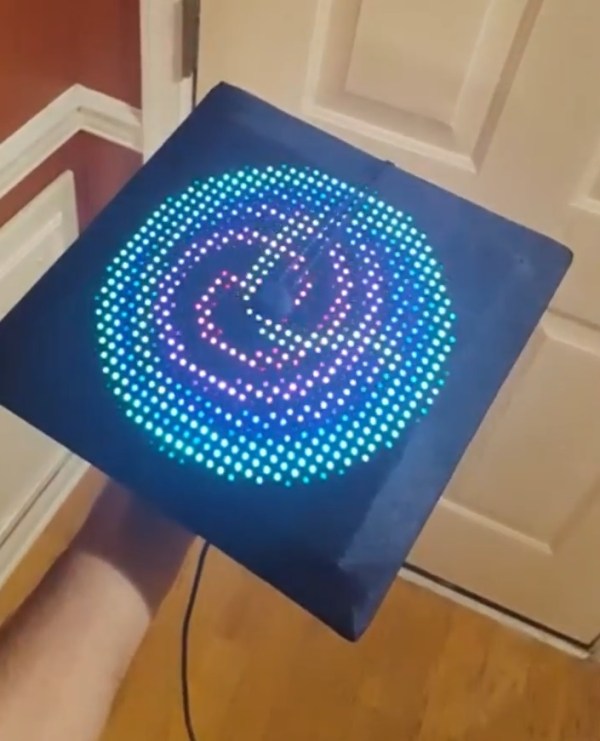
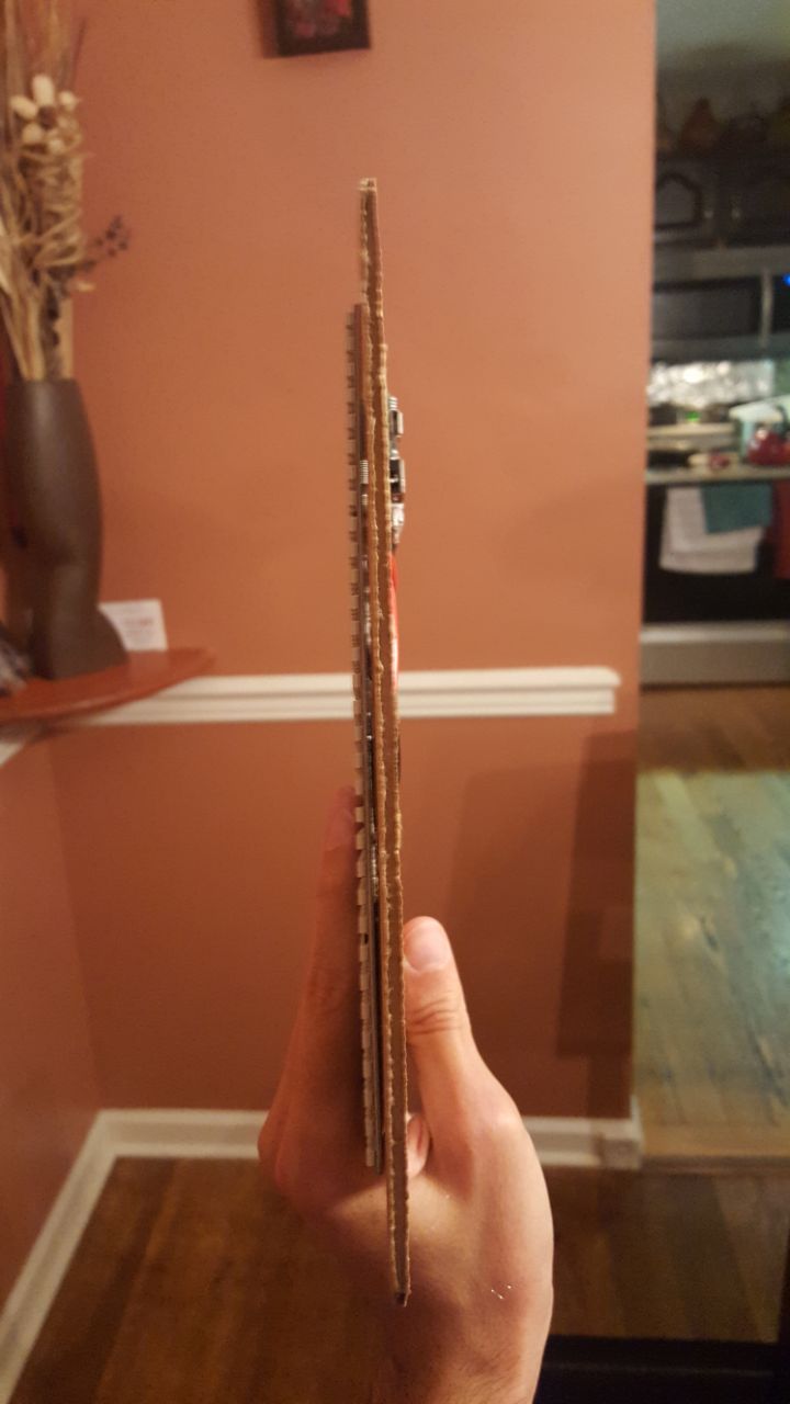
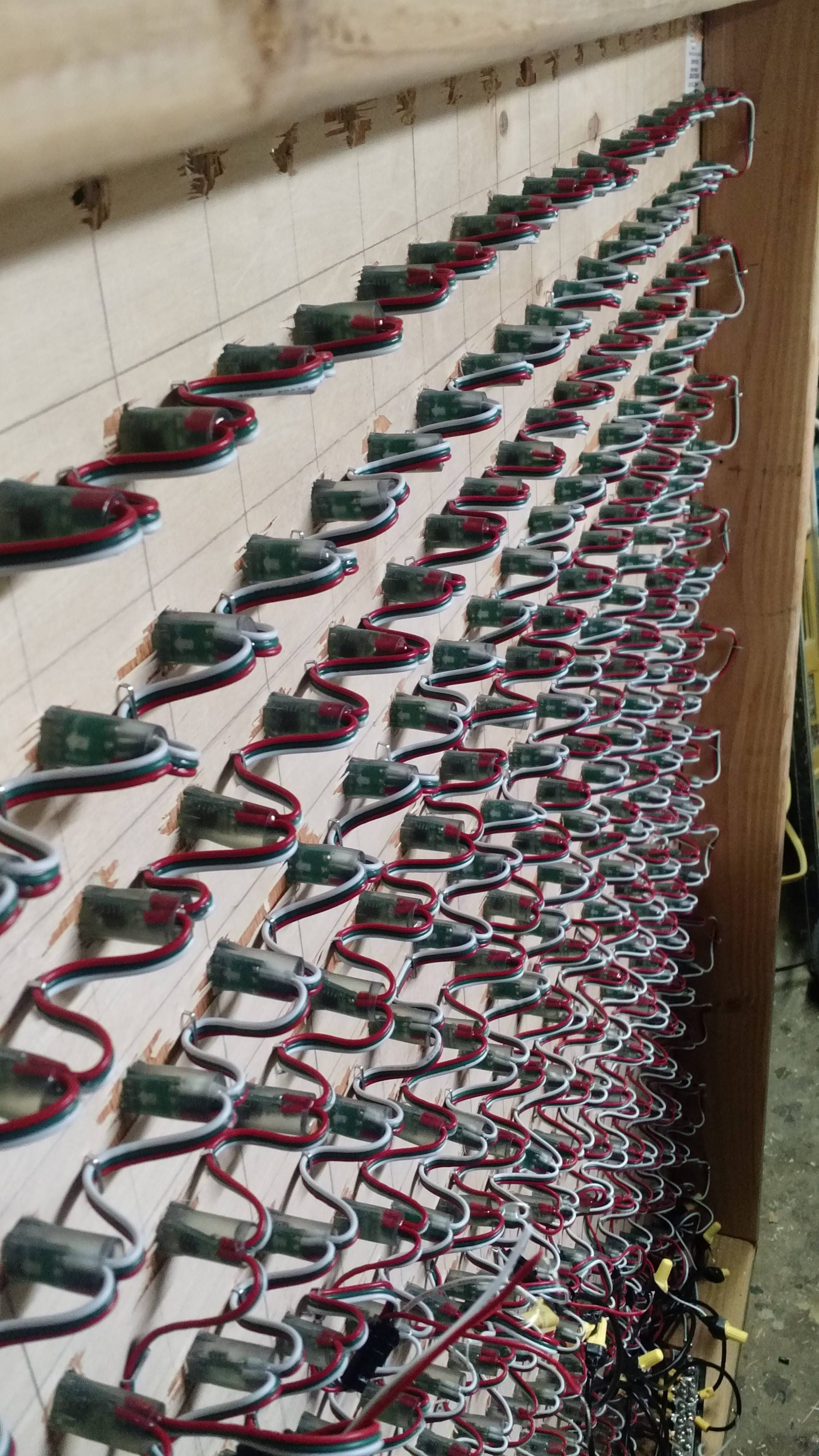
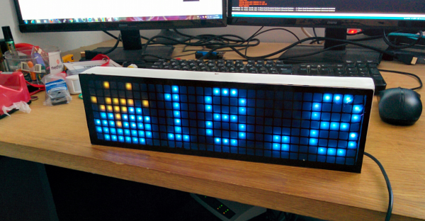
Mini Retro PET Computer

There was a time that the Commodore PET was the standard computer at North American schools. It’s all-in-one, rugged construction made it ideal for the education market and for some of us, the PET started a life-long love affair with computers. [Ruiz Brothers] at Adafruit has come up with a miniature PET model run on a microcontroller and loaded up with a green LED matrix for a true vintage look.

While not a working model of a PET, the model runs on an Adafruit Feather M0 Basic Proto which is an Atmel ATSAMD21 Cortex M0 microcontroller and can display graphics on Adafruit’s 16×9 charlieplexed led matrix.The ATSAMD21 is the chip used in the Arduino Zero, so I’m sure we’ll see more of this chip in the future. Like all of the tutorials at Adafruit, this one is very detailed with step-by-step animated pictures to help you along. Obviously, you don’t need the exact hardware that they’re using, but if you’re putting in an order from Adafruit anyway, why not?

The plans for the 3D printed PET are available for free, so even if you don’t want to put their LED matrix and microcontroller in it, you can still print yourself out a great looking prop and 3D printing the PET will only use about a dollar’s worth of filament. Of course, while this is a cool retro model, if you have a Commodore PET lying around, you could probably do something else with it. We don’t, so that sound you hear is the sound of our 3D printer printing up the past.

Continue reading “Mini Retro PET Computer”

LED Matrix Shades You Can Actually See Though

[Gal Pavlin] admits to enjoying the occasional dance music show. For those who have never been to one, LED one-upmanship at these shows is a real and terrible thing, so much so that an entire market exists around it. To that end, [Gal] built a pretty spiffy set of LED glasses.

It took quite a bit of work to arrive at the final design. All the circuitry and LEDs fit entirely within the envelope of the lenses on a pair of sunglass frames of dubious parentage. The batteries squeeze in between the user’s head and temples.

On top of the clever packaging is an equally impressive set of features. Each lens is a matrix of 69 LEDs. They have an accelerometer, a microphone, and a light sensor. There’s even a vibrating alert motor, which we feel is just showing off.  Best of all, you can actually see through the glasses, thanks to clever layout and very tiny LEDs.

The device requires a tag connect or soldering on a pigtail to program. If you’d like to build one yourself all the files are available on [Gavin]’s site. There’s a video of it in operation after the break.

Continue reading “LED Matrix Shades You Can Actually See Though”

Cellular Automata Explorer

Well all know cellular automata from Conway’s Game of Life which simulates cellular evolution using rules based on the state of all eight adjacent cells. [Gavin] has been having fun playing with elementary cellular automata in his spare time. Unlike Conway’s Game, elementary automata uses just the left and right neighbors of a cell to determine the next cell ahead in the row. Despite this comparative simplicity, some really complex patterns emerge, including a Turing-complete one.

[Gavin] started off doing the calculations by hand for fun. He made some nice worksheets for this. As we can easily imagine, doing the calculations by hand got boring fast. It wasn’t long before his thoughts turned to automating his cellular automata. So, he put together an automatic cellular automator. (We admit, we are having a bit of fun with this.)

This could have been a quick software project but half the fun is seeing the simulations on a purpose-built ecosystem. The files to build the device are hosted on Thingiverse. Like other cellular automata projects, it uses LED matrices to display the data. An Arduino acts as the brain and some really cool retro switches from the world’s most ridiculously organized electronics collection finish the look of the project.

To use, enter the starting condition with the switches at the bottom. The code on the Arduino then computes and displays the pattern on the matrix. Pretty cool and way faster than doing it by hand.

FPGA Powers Blazingly Fast LED Matrix Audio Visualizer

[Sam Miller], [Sahil Gupta], and [Mashrur Mohiuddin] worked together on a very fast LED matrix display for their final project in ECE 5760 at Cornell University.

Real time!
Real time!

They started, as any good engineering students, by finding a way to make their lives easier. [Sam] had built a 32×32 LED matrix for another class. So, they made three more and ended up with a larger and more impressive 64×64 LED display.

They claim their motivation was the love of music, but we have a suspicion that the true reason was the love all EEs share for unnaturally bright LEDs; just look at any appliance at night and try not be blinded.

The brains of the display is an Altera DE2-115 FPGA board. The code is all pure Verilog. The FFT and LED control are implemented in hardware on the FPGA; none of that Altera core stuff. To generate images and patterns they wrote a series of python scripts. But for us it’s the particle test shown in the video below that really turns our head. This system is capable of tracking and reacting to a lot of different elements on the fly why scanning the display at about 310 FPS. They have tested display scanning at twice that speed but some screen-wrap artifacts need to be worked out before that’s ready for prime time.

The team has promised to upload all the code to GitHub, but it will likely be a while before the success hangover blows over and they can approach the project again. You can view a video interview and samples of the visualizations in the videos after the break.

Thanks to their Professor, [Bruce Land], for submitting the tip! His students are always doing cool things. You can even watch some of his excellent courses online if you like: Here’s one on the AVR micro-controller.

Continue reading “FPGA Powers Blazingly Fast LED Matrix Audio Visualizer”

Aurora Painting

“Arduino Borealis” Combines LEDs And Paint

[Stef Cohen] decided to combine three different artistic mediums for her latest project. Those are painting, electronics, and software. The end goal was to recreate the aurora borealis, also known as the northern lights, in a painting.

The first step was to make the painting. [Stef] began with a shadow box. A shadow box is sort of like a picture frame that is extra deep. A snowy scene was painted directly onto the front side of the glass plate of the shadow box using acrylic paint. [Stef] painted the white, snowy ground along with some pine trees. The sky was left unpainted, in order to allow light to shine through from inside of the shadow box. A sheet of vellum paper was fixed to the inside of the glass pane. This serves to diffuse the light from the LEDs that would eventually be placed inside the box.

Next it was time to install the electronics. [Stef] used an off-the-shelf RGB LED matrix from Adafruit. The matrix is configured with 16 rows of 32 LEDs each. This was controlled with an Arduino Uno. The LED matrix was mounted inside the shadow box, behind the vellum paper. The Arduino code was easily written using Adafruit’s RGB Matrix Panel library.

To get the aurora effect just right, [Stef] used a clever trick. She took real world photographs of the aurora and pixelated them using Photoshop. She could then sample the color of each pixel to ensure that each LED was the appropriate color. Various functions from the Adafruit library were used to digitally paint the aurora into the LED matrix. Some subtle animations were also included to give it an extra kick.

1768 LEDs, Because 96 Just Wasn’t Enough

Some people would look at a massive 6’x4′ LED matrix hanging on the wall playing animations and be happy with the outcome. But [Ben] just isn’t one of those people. The original FLED (Fantastic LED thingy) was eight rows of twelve addressable LEDs for a total of 96 pixels. This spring he upped his game and retrofitted the display with 1768 LEDs.

It wasn’t simply an issue of restlessness, the original build suffered from LEDs dying. We actually featured it for that reason as a Fail of the Week.  This is not strictly a hobby project, it’s hanging on the wall in the Supplyframe offices, so pulling it down frequently to fix broken parts is not ideal.

fled-reborn-LED-layoutTo make FLED more reliable [Ben] sourced strips of the new APA102 LEDs which we looked at back in December. They use an SPI bus instead of the bizarre timing scheme of the WS2812. At first glance you’d think this would mean easier assembly compared to soldering both sides of each of the original 96-pixels. These do come in strips, but laying out 52×34 still means soldering to the ends of each row.

A lot of love went into making sure those rows were laid out perfectly. A sheet of white foamed PVC serves as the substrate. There is grounding braid on either end of the rows, one is the voltage bus, the other is ground. It fits the original enclosure which is acrylic and does a great job of diffusing the light. I’ve seen it in person and it looks pretty much perfect!

It’s not just the physical layout of this many pixels that is a challenge. Pushing the data to all of them is much harder than it was with 96. [Ben] transitioned away from RaspberryPi. He considered using a Teensy 3.1 and ESP8266 but the WiFi of these cheap modules is far too slow to push frame information from a remote box. In the end it’s a BeagleBone Black that drives the reborn display. This is a great choice since there’s plenty of power under the hood and a traditional (and much faster) WiFi dongle can be used.

Don’t miss the animation demos found after the break.

Continue reading “1768 LEDs, Because 96 Just Wasn’t Enough”

Tetris

Arduino Tetris On A Multiplexed LED Matrix

[Alex] needed a project for his microcomputer circuits class. He wanted something that would challenge him on both the electronics side of things, as well as the programming side. He ended up designing an 8 by 16 grid of LED’s that was turned into a game of Tetris.

He arranged all 128 LED’s into the grid on a piece of perfboard. All of the anodes were bent over and connected together into rows of 8 LED’s. The cathodes were bent perpendicularly and forms columns of 16 LED’s. This way, if power is applied to one row and a single column is grounded, one LED will light up at the intersection. This method only works reliably to light up a single LED at a time. With that in mind, [Alex] needed to have a very high “refresh rate” for his display. He only ever lights up one LED at a time, but he scans through the 128 LED’s so fast that persistence of vision prevents you from noticing. To the human eye, it looks like multiple LED’s are lit up simultaneously.

[Alex] planned to use an Arduino to control this display, but it doesn’t have enough outputs on its own to control all of those lights. He ended up using multiple 74138 decoder/multiplexer IC’s to control the LED’s. Since the columns have inverted outputs, he couldn’t just hook them straight up to the LED’s. Instead he had to run the signals through a set of PNP transistors to flip the logic. This setup allowed [Alex] to control all 128 LED’s with just seven bits, but it was too slow for him.

His solution was to control the multiplexers with counter IC’s. The Arduino can just increment the counter up to the appropriate LED. The Arduino then controls the state of the LED using the active high enable line from the column multiplexer chip.

[Alex] wanted more than just a static image to show off on his new display, so he programmed in a version of Tetris. The controller is just a piece of perfboard with four push buttons. He had to work out all of the programming to ensure the game ran smoothly while properly updating the screen and simultaneously reading the controller for new input. All of this ran on the Arduino.

Can’t get enough Tetris hacks? Try these on for size.