[Helge Fyske (LA6NCA)] may not be an actual spy — then again, he may be; if he’s good at it, we wouldn’t know — but he has built a couple of neat vacuum tube spy radios in the past. And there’s no better test for such equipment than to haul it out into the field and try to make some contacts. But how do you power such things away from the bench?
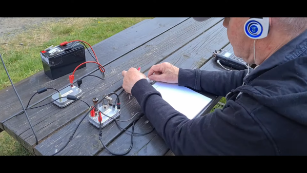
To answer that question, skip ahead to the 3:18 mark of the video below, where [Helge] shows off his whole retro rig, including the compact 250-volt power supply he built for his two-tube 80-m Altoids tin spy transceiver. In the shack, [Helge] powers it with a bench power supply of his own design to provide the high anode voltage needed for the tubes, as well as 12 volts for their heaters. Portable operations require a more compact solution, preferably one that can be run off a battery small enough to pack in.
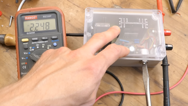
By building his power supply in a tin, [Helge] keeps to his compact build philosophy. But the circuit is all solid state, which is an interesting departure for him. The switch-mode supply uses a 4047 astable multivibrator chip as a 50-kHz oscillator, which switches back and forth between a pair of MOSFETs to drive a transformer. This steps up the 12-volt input to 280 volts AC, which is then rectified, filtered, and regulated to 250 volts DC.
To round out his spy rig, [Helge] also designed a tiny Morse key, which appears to be 3D printed and fits in its own tin, and a compact dipole antenna. Despite picking what appears to be a challenging location — the bottom of a steep-sided fjord — [Helge] was easily able to make contacts over a distance of 400 km. His noise floor was remarkably low, a testament to the solid design of his power supply. Including the sealed lead acid battery, the whole kit is compact and efficient, and it’s a nice example of what vacuum tubes and solid state can accomplish together.
Continue reading “Spy Radio Setup Gets A Tiny Power Supply For Field Operations” →


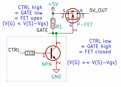 Here’s a simple FET circuit that lets you switch power to, say, a USB port, kind of like a valve that interrupts the current flow. This circuit uses a P-FET – to turn the power on, open the FET by bringing the GATE signal down to ground level, and to switch it off, close the FET by bringing the GATE back up, where the resistor holds it by default. If you want to control it from a 3.3 V MCU that can’t handle the high-side voltage on its pins, you can add a NPN transistor section as shown – this inverts the logic, making it into a more intuitive “high=on, low=off”, and, you no longer risk a GPIO!