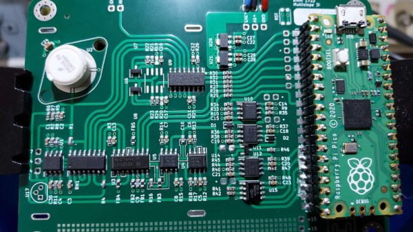
In a world where an analogue to digital converter is all too often an integrated peripheral buried inside a microcontroller, it’s easy to forget how simple these devices can be when built from first principles. An entry in our Op-Amp Challenge from [NNNI] demonstrates this perfectly, it’s a high resolution multi-slope ADC for instrumentation purposes, constructed using a mixture of op-amps, logic chips, and a Raspberry Pi Pico. Best of all, it’s easy to understand, so there’s little of that analogue mystique to worry about.
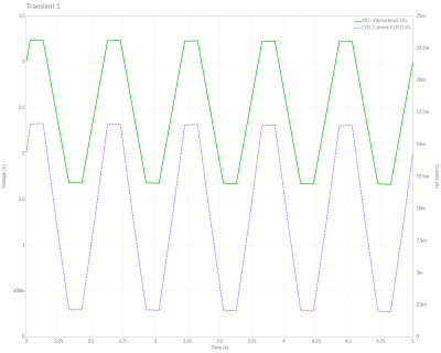
This type of ADC measures an analogue value by counting how long it takes to charge a capacitor to that voltage. A simple version that measures charge time has a few drawbacks, so this project goes from single slope to multi slope by measuring both charge and discharge times compared to the voltage. Pay attention to component matching and reference stability, and such a design can offer a very high resolution measurement.
The value in this project lies not only in the design itself, but also in the extremely comprehensive description of its operation, which should teach most readers a thing or two. That curvy-line PCB is rather nice, too. We used single slope ADCs to read analogue joysticks back in the day, but we certainly learned something here. Want to see another? This isn’t the first dual slope ADC we’ve seen.