Hyper Links And Hyperfunctional Text CAD

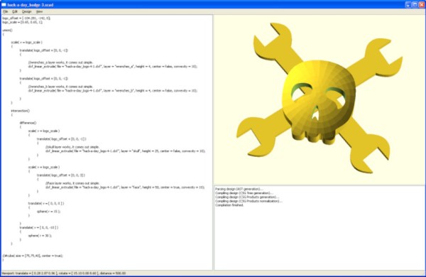
Strong opinions exist on both sides about OpenSCAD. The lightweight program takes megabytes of space, not gigabytes, so many people have a copy, even if they’ve never written a shape. Some people adore the text-only modeling language, and some people abhor the minimal function list. [Johnathon ‘Zalo’ Selstad] appreciates the idea but wants to see something more robust, and he wants to see it in your browser. His project CascadeStudio has a GitHub repo and a live link so you can start tinkering in a new window straight away.

Continue reading “Hyper Links And Hyperfunctional Text CAD”

Keycap Customizer Brings All Your Caps To The Board

With bright colors and often intricate designs, after the physical shape of a keyboard the most conspicuous elements are surely the keycaps. Historically dictated by the stem of the key switch it attaches to, keycaps come in a variety of sizes, colors, profiles, and designs. As they necessarily include small features with tight tolerances to fit the stem of their key switch, injection molding is the classic manufacturing technique for a keycap. But as hobbyist 3D printing matures and resin printers become more accessible, home keycap manufacturing is increasingly good option. Instead of designing each cap by hand, consider trying [rsheldiii]’s KeyV2 OpenSCAD script to create custom caps with ease.

To cover the basics, KeyV2 can generate full keycap sets with Cherry or Alps stems, in the SA, DSA, DCS profiles (and more!) for any typically sized keyboard. Generating a particular cap of arbitrary profile, position, and size is just a short chain of function calls away. But standard keycap sets aren’t the highlight of this toolset.

If you’re not an OpenSCAD aficionado yet, visit [Brian Benchoffs] great getting-started guide or our other coverage to get a feel for what the tool can do. Part of OpenSCAD’s attraction is that it is the the paragon of parametric modeling. It’s declarative part files ensure that no parameter goes undefined, which is a perfect fit for KeyV2.

The root file upon which all caps are based on has about 150 keycap parameters which can be tweaked, and that’s before more elaborate customization. Making simple “artisan” caps is a snap, as the magic of OpenSCAD means the user can perform any Boolean operations they need on top of the fully parameterized keycap. Combining an arbitrary model with a keycap is one union() away. See the README for examples.

For the prospective user of KeyV2 worried about complexity; don’t be, the documentation is a treat. Basic use to generate standard keycaps is simple, and there are plenty of commented source files and examples to make more complex usage easy. Thinking about a new keyboard? Check out our recent spike in clacky coverage.

Quick 3D-Printed Airfoils With These OpenSCAD Helpers

You know how it is. You’re working on a project that needs to move air or water, or move through air or water, but your 3D design chops and/or your aerodynamics knowledge hold you back from doing the right thing? If you use OpenSCAD, you have no excuse for creating unnecessary turbulence: just click on your favorite foil and paste it right in. [Benjamin]’s web-based utility has scraped the fantastic UIUC airfoil database and does the hard work for you.

While he originally wrote the utility to make the blades for a blower for a foundry, he’s also got plans to try out some 3D printed wind turbines, and naturally has a nice collection of turbine airfoils as well.

If your needs aren’t very fancy, and you just want something with less drag, you might also consider [ErroneousBosch]’s very simple airfoil generator, also for OpenSCAD. Making a NACA-profile wing that’s 120 mm wide and 250 mm long is as simple as airfoil_simple_wing([120, 0030], wing_length=250);

If you have more elaborate needs, or want to design the foil yourself, you can always plot out the points, convert it to a DXF and extrude. Indeed, this is what we’d do if we weren’t modelling in OpenSCAD anyway. But who wants to do all that manual labor?

Between open-source simulators, modelling tools, and 3D printable parts, there’s no excuse for sub-par aerodynamics these days. If you’re going to make a wind turbine, do it right! (And sound off on your favorite aerodynamics design tools in the comments. We’re in the market.)

There’s An Engineer In Germany I’d Like A Word With; Tale Of A Crumbling Volkswagen Lock

In common with quite a few in the hardware hacking community, I have a fondness for older vehicles. My “modern” ride is an older vehicle by today’s standards, a Volkswagen Polo 6N made in the late 1990s. It’s by my estimation a Good Car, having transported me reliably back and forth across the UK and Europe for several years.

Last week though, it let me down. Outside the church in a neighbouring village the driver’s door lock failed, leaving me with my igniton key stuck in the door, and a mildly embarrassing phone call to my dad to bring the Torx driver required to remove the assembly and release it. I am evidently not 1337 enough, I don’t carry a full set of Torx bits with me everywhere I go. The passenger side lock has never worked properly while I’ve had the car, and this is evidently my cue to sort it all out.

Continue reading “There’s An Engineer In Germany I’d Like A Word With; Tale Of A Crumbling Volkswagen Lock”

Finding Perfect Part Fits With The Goldilocks Approach (and OpenSCAD)

There is something to be said for brute force or trial-and-error approaches to problems, especially when finding a solution has an empirical element to it. [Tommy] perceived that to be the case when needing to design and 3D print servo horns that would fit factory servos as closely as possible, and used OpenSCAD to print a “Goldilocks array” from which it was possible to find a perfect match for his printer by making the trial and error process much more efficient. By printing one part, [Tommy] could test-fit dozens of options.

What made doing this necessary is the fact that every 3D printer has some variance in how accurately they will reproduce small features and dimensions. A 6.3 mm diameter hole in a CAD model, for example, will not come out as exactly 6.3 mm in a 3D-printed object. It will be off by some amount, but usually consistently so. Therefore, one way around this is to empirically determine which measurements result in a perfect fit, and use those for production on that specific 3D printer.

That’s exactly what [Tommy] did, using OpenSCAD to generate an array of slightly different sizes and shapes. The array gets printed out, servos are test-fitted to them, and whichever option fits best has its dimensions used for production. This concept can be implemented in any number of ways, and OpenSCAD makes a decent option due to its programmatic nature. Interested in OpenSCAD? It will run on nearly any hardware, and you can get up and running with the basics in probably less than ten minutes.

Can Solder Paste Stencils Be 3D Printed? They Can!

3D printed solder paste stencil, closeup.

[Jan Mrázek]’s  success with 3D printing a solder paste stencil is awfully interesting, though he makes it clear that it is only a proof of concept. There are a lot of parts to this hack, so let’s step through them one at a time.

First of all, it turns out that converting a PCB solder paste layer into a 3D model is a bit of a challenge. A tool [Jan] found online didn’t work out, so he turned to OpenSCAD and wrote a script (available on GitHub) which takes two DXF files as input: one for the board outline, and one for the hole pattern. If you’re using KiCad, he has a Python script (also on GitHub) which will export the necessary data.

The result is a 3D model that is like a solder paste mask combined with a raised border to match the board outline, so that the whole thing self-aligns by fitting on top of the PCB. A handy feature, for sure. [Jan] says the model pictured here printed in less than 10 minutes. Workflow-wise, that certainly compares favorably to waiting for a stencil to arrive in the mail. But how do the actual solder-pasting results compare?

3D printed solder stencil on PCB, after applying solder paste.

[Jan] says that the printed stencil had a few defects but it otherwise worked fine for 0.5 mm pitch ICs and 0402 resistors, and the fact that the 3D printed stencil self-registered onto the board was a welcome feature. That being said, it took a lot of work to get such results. [Jan]’s SLA printer is an Elegoo Mars, and he wasn’t able to have it create holes for 0.2 mm x 0.5 mm pads without first modifying his printer for better X/Y accuracy.

In the end, he admits that while a functional DIY solder stencil can be 3D printed in about 10 minutes, it’s not as though professionally-made stencils that give better results are particularly expensive or hard to get. Still, it’s a neat trick that could come in handy. Also, a quick reminder that we stepped through how to make a part in OpenSCAD in the past, which should help folks new to OpenSCAD make sense of [Jan]’s script.

Design And Construction With Copper Pipe

Copper is a material with many applications; typically, it’s used for electrical wiring or in applications where good heat conductivity is a requirement. However, it can also make for an attractive material in furnishings, which [Andrei Erdei] decided to explore.

A render of the coffee table design, exported from OpenSCAD into Fusion360.

[Andrei]’s work began in OpenSCAD, where he wrote scripts to enable the quick and easy assembly of various designs. The modular nature of commercially-available copper pipe and fittings allows complex structures to be assembled, particularly if you’re a fan of 90-degree bends. The final renders of some of these designs are impressive, with the coffee table design a particular highlight. Staying conceptual wasn’t enough, however, so [Andrei] set out to build one of his designs. Constructing a table lamp shroud out of copper parts was successful, though the real components have flanges and other features that aren’t represented in the rendering.

It’s a project that shows the value of tools such as OpenSCAD to aid the design process before committing to cutting real-world materials. While the designs on screen aren’t perfect representations of what’s possible in reality, it still proves to be a useful guide.

We’re a fan of the aesthetic, and would love to see more done with copper pipe as a construction kit. Global ore prices may limit experimentation, however. Alternatively, you can always harvest the metal from scrap!