Altoids Tin Spy Radio Goes Solid State

[Helge Fykse (LA6NCA)] has a type, as they say. At least as far as radios are concerned, he seems to prefer elegant designs that keep the BOM to the minimum needed to get the job done. And Altoids tins — he really seems to like putting radios in Altoids tins.

This QRP transceiver for the 60-meter amateur radio band is a perfect example of that ethos. For the unfamiliar, QRP is Morse code shorthand for decreased power, and is generally used when hams are purposely building and operating radios that radiate very little power, typically below a watt. For this transceiver, [Helge] chose to use modern components, a marked but interesting departure from his recent tube-powered spy radios. The design is centered on a custom oscillator board he designed using an Arduino Pro Mini and an Si5351 oscillator chip. Other components include an ADE-1ASK frequency mixer, an antenna tuner module that can be swapped out for operating on different bands, a receiver that’s little more than a couple of op-amps, and a Darlington pair for an RF power amplifier. Everything fits neatly on a piece of copper-clad board inside the tin box.

As is his tradition, [Helge] was on the air in the field with this radio almost before the solder had time to cool. His first contact was a 240-km shot to a friend, who reported a fine signal from this little gem. And that’s with just powering it off a 9-volt battery when it’s designed to the typical 12-volt supplies hams favor; he estimates this resulted in a signal of about 200 mW. Not too shabby.

Honestly, we’d love to learn more about that oscillator board [Helge] used, and maybe get a schematic for it. We found a little bit about it on his web page, but not the juicy details. If you’re out there, [Helge], please share the wealth.

Continue reading “Altoids Tin Spy Radio Goes Solid State”

Clock Hack Gives DEC Rainbow A New Lease On Life

In retrocomputing circles, it’s often the case that the weirder and rarer the machine, the more likely it is to attract attention. And machines don’t get much weirder than the DEC Rainbow 100-B, sporting as it does both Z80 and 8088 microprocessors and usable as either a VT100 terminal or as a PC with either CP/M or MS-DOS. But hey — at least it got the plain beige box look right.

Weird or not, all computers have at least a few things in common, a fact which helped [Dr. Joshua Reichard] home in on the problem with a Rainbow that was dead on arrival. After a full recapping — a prudent move given the four decades since the machine was manufactured — the machine failed to show any signs of life. The usual low-hanging diagnostic fruit didn’t provide much help, as both the Z80 and 8088 CPUs seemed to be fine. It was then that [Joshua] decided to look at the heartbeat of the machine — the 24-ish MHz clock shared between the two processors — and found that it was flatlined.

Unwilling to wait for a replacement, [Joshua] cobbled together a temporary clock from an Arduino Uno and an Si5351 clock generator. He connected the output of the card to the main board, whipped up a little code to generate the right frequency, and the nearly departed machine sprang back to life. [Dr. Reichard] characterizes this as a “defibrillation” of the Rainbow, and while one hates to argue with a doctor — OK, that’s a lie; we push back on doctors all the time — we’d say the closer medical analogy is that of fitting a temporary pacemaker while waiting for a suitable donor for a transplant.

This is the second recent appearance of the Rainbow on these pages — [David] over at Usagi Electric has been working on the graphics on his Rainbow lately.

An LM386 Oscillator Thanks To Tungsten Under Glass

Once ubiquitous, the incandescent light bulb has become something of a lucerna non grata lately. Banned from home lighting, long gone from flashlights, and laughed out of existence by automotive engineers, you have to go a long way these days to find something that still uses a tungsten filament.

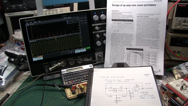
Strangely enough, this lamp-stabilized LM386 Wien bridge oscillator is one place where an incandescent bulb makes an appearance. The Wien bridge itself goes back to the 1890s when it was developed for impedance measurements, and its use in the feedback circuits of vacuum tube oscillators dates back to the 1930s. The incandescent bulb is used in the negative feedback path as an automatic gain control; the tungsten filament’s initial low resistance makes for high gain to kick off oscillation, after which it heats up and lowers the resistance to stabilize the oscillation.

For [Grug Huler], this was one of those “just for funsies” projects stemming from a data sheet example circuit showing a bulb-stabilized LM386 audio oscillator. He actually found it difficult to source the specified lamp — there’s that anti-tungsten bias again — but still managed to cobble together a working audio oscillator. The first pass actually came in pretty close to spec — 1.18 kHz compared to the predicted 1.07 kHz — and the scope showed a very nice-looking sine wave. We were honestly a bit surprised that the FFT analysis showed as many harmonics as it did, but all things considered, the oscillator performed pretty well, especially after a little more tweaking. And no, the light bulb never actually lights up.

Thanks to [Grug] for going down this particular rabbit hole and sharing what he learned. We love builds like this that unearth seemingly obsolete circuits and bring them back to life with modern components. OK, calling the LM386 a modern component might be stretching things a bit, but it is [Elliot]’s favorite chip for a reason.

Continue reading “An LM386 Oscillator Thanks To Tungsten Under Glass”

Spy Transceiver Makes Two Tubes Do The Work Of Five

Here at Hackaday, we love following along with projects as they progress. That’s especially true when a project makes a considerable leap in terms of functionality from one version to another, or when the original design gets more elegant. And when you get both improved function and decreased complexity at the same time? That’s the good stuff.

Take the recent improvements to a vacuum tube “spy radio” as an example. Previously, [Helge (LA6NCA)] built both a two-tube transmitter and a three-tube receiver, either of which would fit in the palm of your hand. A little higher math seems to indicate that combining these two circuits into a transceiver would require five tubes, but that’s not how hams like [Helge] roll. His 80-m CW-only transceiver design uses only two tubes and a lot of tricks, which we admit we’re still wrapping our heads around. On the receive side, one tube serves as a mixer/oscillator, combining the received signal with a slightly offset crystal-controlled signal to provide the needed beat frequency. The second tube serves as the amplifier, both for the RF signal when transmitting, and for audio when receiving.

The really clever part of this build is that [Helge] somehow stuffed four separate relays into the tiny Altoids tin chassis. Three of them are used to switch between receive and transmit, while the fourth is set up as a simple electromagnetic buzzer. This provides the sidetone needed to effectively transmit Morse code, and is about the simplest way we’ve ever seen to address that need. Also impressive is how [Helge] went from a relatively expansive breadboard prototype to a much more compact final design, and how the solder was barely cooled before he managed to make a contact over 200 km. The video below has all the details.

Continue reading “Spy Transceiver Makes Two Tubes Do The Work Of Five”

Two-Tube Spy Transmitter Fits In The Palm Of Your Hand

It’s been a long time since vacuum tubes were cutting-edge technology, but that doesn’t mean they don’t show up around here once in a while. And when they do, we like to feature them, because there’s still something charming, nay, romantic about a circuit built around hot glass and metal. To wit, we present this compact two-tube “spy radio” transmitter.

From the look around his shack — which we love, by the way — [Helge Fykse (LA6NCA)] really has a thing for old technology. The typewriter, the rotary phones, the boat-anchor receiver — they all contribute to the retro feel of the space, as well as the circuit he’s working on. The transmitter’s design is about as simple as can be: one tube serves as a crystal-controlled oscillator, while the other tube acts as a power amplifier to boost the output. The tiny transmitter is built into a small metal box, which is stuffed with the resistors, capacitors, and homebrew inductors needed to complete the circuit. Almost every component used has a vintage look; we especially love those color-coded mica caps. Aside from PCB backplane, the only real nod to modernity in the build is the use of 3D printed forms for the coils.

But does it work? Of course it does! The video below shows [Helge] making a contact on the 80-meter band over a distance of 200 or so kilometers with just over a watt of power. The whole project is an excellent demonstration of just how simple radio communications can be, as well as how continuous wave (CW) modulation really optimizes QRP setups like this.

Continue reading “Two-Tube Spy Transmitter Fits In The Palm Of Your Hand”

A Practical Glue Stick Oscillator

A few months ago we brought you some experiments from [Bill Meara, N2CQR], in which he investigated the use of a glue stick as the former for a permeability tuned inductor. His set-up was very much in the spirit of experimentation, and we’re very pleased to now see [Nick, M0NTV] has taken the idea and demonstrated it for the 7 MHz, or 40 meter, amateur radio band.

The result can be seen in the video below the break, and is housed in a tin enclosure that we’re guessing once contained toffees. The oscillator circuit comes courtesy of [Ashar Farhan VU2ESE] of BitX transceiver fame, but we’re most interested in the glue stick coil former which makes use of a small bracket for stability. With the glue removed, he’s mounted a ferrite ring in its glue carrier which is moved in and out of the coil. We’re guessing this could also be done with other permeability-altering materials, for example we’d follow [VU2ESE]’s lead and try a piece of brass.

The knurled glue feed knob protrudes through a hole in the tin, and we’re guessing there’s enough separation for an operator’s hand not to drag the frequency too much. All in all given that variable capacitors are now something of a rarity, it makes for a useful demonstration of a very cheap replacement. Meanwhile, you can read our notes on [N2CQR]’s work here.

Continue reading “A Practical Glue Stick Oscillator”

Lamp Flashing Module Is Perfect For Automotive Use

Modern cars tend to have quite advanced lighting systems, all integrated under the control of the car’s computer. Back in the day, though, things like brake lights and indicators were all done with analog electronics. If your classic car needs a good old-fashioned flasher module, you might find this build from [DIY Guy Chris] useful.

It’s an all-analog build, with no need for microcontrollers or other advanced modern contrivances. Instead, a little bipolar PNP transistor and a beefier NPN MOSFET as an oscillator, charging and discharging a capacitor to create the desired flashing behavior. Changing the size of the main capacitor changes the flash rate. The MOSFET is chosen as running 12 volt bulbs requires a decent amount of current. The design as drawn is intended to run up to eight typical automotive bulbs, such as you might find in indicator lamps. However, [Chris] demonstrates the circuit with just four.

Flasher circuits were in regular use well into the 1990s. The original Mazda Miata has a very similar circuit tucked up under the dashboard to run the turn signals. These circuits can be hard to find for old cars, so building your own may be a useful workaround if you’re finding parts hard to come by. Video after the break.

Continue reading “Lamp Flashing Module Is Perfect For Automotive Use”