The Three Chip Retrocomputer

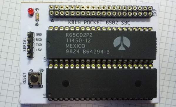
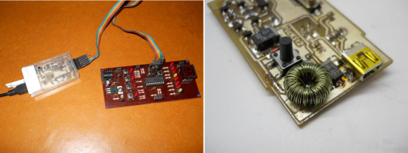
Where homebrew computers are usually complex bundles of wires and chips, [Mike]’s own single board computer is not. It’s a three-chip computer with only a CPU, RAM, and a microcontroller that is able to emulate the retrocomputers of yore.

Normally, a homebrew computer project requires some amount of ‘glue’ logic – a few NAND, OR, or inverters to combine signals and send them where they’re needed for address decoding. This tiny pocket computer doesn’t need any of that; all the address decoding is done on a 40-pin PIC microcontroller.

With 64kB on the PIC 18F46K22, there’s enough space for all the address decoding logic, space for a pseudo ACIA mapped onto the $DF page, and a ROM image that provides a monitor program and a copy of BASIC. Basically, with the addition of a USB to serial adapter, this is a three chip 6502 single board computer, and with the right ROM monitor can emulate an Apple I, Woz monitor included.

Yes, 6502 projects are a dime a dozen, but [Mike]’s work with the address decoding logic on the microcontroller is top-notch. There are a few remaining chip select lines in his schematic, and with another microcontroller it would be easy to add VGA out, a compact flash adapter, or some other really cool peripherals. Good thing there’s an expansion port on this thing.

Single Digit Numitron Clock

numitronClock

The above may look like a Nixie tube, but it’s a Numitron: the Nixie’s lower-voltage friend, and part of [pinomelean’s] single-digit Numitron clock. If you’re unfamiliar with Numitrons, we suggest you take a look at our post from a few years ago, which includes a helpful tutorial to catch you up to speed.

[pinomelean] built this little device to capture a steampunk-ish look on the cheap for a clock small enough to fit on a wrist. The build uses a PIC16F84A uC and a 4MHz crystal on a custom PCB. A small button on the side lets the wearer set the time. Similar to the Vibrating Timepiece from last month, the Numitron clock isn’t perfect, though it is more accurate: gaining only one minute every 3 days.

Check out the video after the break to see it being set and keeping track of the time. It may take a moment to understand how to read the clock, though. Each of the four LEDs indicates where the number in the Numitron tube belongs. The LEDs light in sequence from left to right, displaying the clock one digit at a time.

Continue reading “Single Digit Numitron Clock”

Tic Tac PIC Pack: A Pocket Programmer

Sure, mint tin housings are great. But you have to defend against shorts, and cutting out holes for ports and buttons is dangerous business. [Daniel] prefers plastic, and he tipped us off about a PICKit2 clone that he designed to fit inside of a tic tac box.

Almost all of the components were salvaged except for the microcontroller and the connectors. He wound his own inductor using the ferrite core from a CFL. [Daniel] had to make a few improvisations for this project. He didn’t have a 20MHz crystal, so he used a 12MHz crystal and tweaked the fuse bits after burning the firmware.

To save space on the board, he soldered wires to RESET, VCC, GND, PGD, and PGC to program the firmware and then removed the wires. The only trouble he had with it was more or less easily solved by replacing two transistors.

You may remember that we linked to his USBasp programmer in a mentos container a few months back. We figure [Daniel] must have some pretty fresh breath.

ARM Debugger For Nearly One Dollar

Oh that title is so misleading. But if you squint your eyes and scratch your noggin it’s almost true. Thanks to the hard work of [Peter Lawrence] it is now possible to hack together an extremely inexpensive CMSIS-DAP ARM debugger.

Let’s talk about function and we’ll get back to cost later. CMSIS-DAP is a standard that gives you the kind of breakpoint control you expect from a proper debugger. In this case [Peter] implemented the standard using 4k words of space on a PIC 16F1454. This lets it talk to the debug port on ARM chips, and the bootloader (also written by him) doubles as a USB-to-UART bridge. Boom, done. OpenOCD (and a couple of other software packages) talks to the PIC and it talks to the ARM. Nice.

Back to the cost question. You can get a 16F1454 for nearly a dollar when you order in quantity. If you cut up an old USB cable, recycle some jumper wire, and already have power and decoupling on hand, you’re in business for nearly one dollar.

Happy Birthday, Son. Here’s Your Very Own Claw Machine

mrclawIf [Will Baden] is in the running for Father of the Year, he’s a shoe-in. His son requested a robot-themed birthday party, so [Will] did what any superhero father would do and built him a toy claw machine.

[Will] harvested many of the parts from copy machines: both the 5V and 24V power supplies, the limit switches, 2/3 of the motors, and the 24V solenoid coil in the claw. The carriage is from a commercial printer. He made many of the mounts, including the ones holding the 3 stepper motors from Pololu.

A PIC16F870 is running the show. [Will] programmed it in assembly using Timer2 for stepper pulsing and RB0 interrupt to drop the claw when the button is pushed. He also added a WDT to get out of code trouble if needed. The claw’s solenoid is driven by a ULN2001A Darlington array. [Will] put a kickback diode on the coil so the pulses don’t go farther than they need to. He formed the fingers of the claw by bending pieces of brake line.

Not your kind of claw? Check out these incredible Wolverine claws!

Continue reading “Happy Birthday, Son. Here’s Your Very Own Claw Machine”

Sucking PIC Firmware Out Of An Old APC Battery Backup

reverse-engineering-pic-firmware-of-APC-power-supply

Looking at this huge Uninterruptible Power Supply we are a little envious. It’s meant to hang on the wall of a utility room and power your critical devices. [Radek Hvizdos] has had it in service for quite some time, and when he started thinking of replacing the internal battery he decided to see if he could also extend the functionality. To do so he needed to get at the firmware of the chip controlling the device. And so began his adventure of dumping the firmware from the read-protected PIC 18F452.

The challenge of dumping code from a write-protected chip is in itself a fun project. But [Radek] was actually interested in fixing bugs and adding features. The wishlist feature we’d be most interested in is a kind of triage for shutting down devices as the internal battery starts to run low. Nice! But starting from scratch with the firmware is a no-go. You can see the two places where he connected to the PCB. The upper is for using a PIC programmer. The lower is an I2C connection used to dump the EEPROM with an improvised Bus Pirate.

In the end it was improper lock bit settings that opened the door to grabbing the firmware. The bootloader section of the PIC is not locked, and neither is the ability to read from FLASH at run-time. These two combined allowed him to write his own code which, when flashed to the bootloader section, dumps the rest of the firmware so that it may be combined into a complete file afterward. Since posting this fascinating article he has made a follow-up about disassembling the code.

Fubarino Contest: Serial Data Transmission

fubarino-contest-serial-data

[Jesus] is helping his cousin learn about microcontrollers. Right now they’re on the subject of serial communications, which turned into a nice way to add a Hackaday Easter Egg.

Using and FTDI chip in conjunction with the PIC 18F4550 (it’s a little soon for them to tackle implementing USB directly) the serial data is shown in a terminal window. At the same time the binary value of each byte is flashed on the PORTD LEDs. When the chip receives the characters “hack” it immediately echos back the recommendation to check out the awesomeness that is Hackaday. He posted the code used in this example as a Gist.


This is an entry in the Fubarino Contest for a chance at one of the 20 Fubarino SD boards which Microchip has put up as prizes!

Continue reading “Fubarino Contest: Serial Data Transmission”