A DIY E-Ink Tank Watch

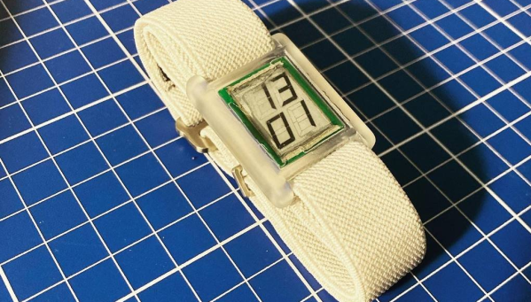
[Augusto Marinucci] liked the classic Cartier Tank series of dress watches aesthetic, but wanted something a bit more techy, with a decent runtime on a single battery. E-Ink displays are often used in such applications, but finding one to fit a custom case design, is a tall order. When ordering one off the shelf is not easy, the solution is to make one from scratch.

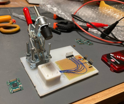
Building a programming jig is a great idea for small-scale production

The article doesn’t have much information on the E-Ink side of things, which is a bit of a shame. But from what we can glean, the segment shapes — in this case, based on the famous Apollo DSKY — are formed in the top copper of a four-layer PCB, using filled and capped vias to connect invisibly from below.

A donor E-Ink display is cut to size with scissors (we don’t know much more than this!) and glued in place around the edge to make the common electrode connection. The display PCB attaches to the control PCB, at the rear using low-profile board-to-board connectors. This board hosts a PIC16 micro, as well as an RV-3028-C7 RTC which keeps time whilst consuming a paltry 45 nA.

Five volts are provided via a MAX1722 low-power boost converter which is fed power from the CR1616 cell via a couple of logic-controllable load switches. With a low-power design such as this, it’s critical to get this correct. Any mistakes here can easily result in a very low runtime. It is easy to over-stress small button cells and kill them prematurely.

The case looks like it’s printed in a translucent resin, with the PCB stack sealed inside with a UV-cured resin pour. It’s not immediately obvious if the rear panel can be removed to access the battery and programming port. There are what appear to be screw holes, so maybe that’s possible, or maybe they’re the rear side of the PCB mounting posts. Who can tell?

If DIY hardware is but too much effort for you, then there’s the option of hacking new firmware onto an existing watch, or perhaps meeting in the middle and making something out of all those junk E-ink tags you can get from time to time?

Thanks to [JohnU] for the tip!

Cockpit Instrument Respectfully Retasked As A Clock

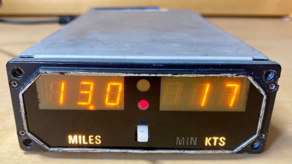
How do you convert an old cockpit instrument into a clock? Easy: just build a circuit that convinces it it’s in the air, and the rest will take care of itself.

Now obviously, little about [porkfreezer]’s conversion of King KI 266 DME into a clock was actually easy; working with avionics rarely is. DME stands for “Distance Measuring Equipment,” an instrument that’s part of the radio navigation suite of many aircraft. DME measures the line-of-sight distance of a plane to a ground station by measuring the time it takes for a signal to return after the plane interrogates it. The plane-mounted equipment includes a UHF transceiver and a display for the cockpit instrument panel, which accepts an analog voltage signal from the transceiver and translates it into a readout on the nice Panaplex digital display.

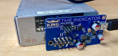
Rather than gutting the thing and just driving the display directly, [porkfreezer] decided to build a circuit to generate the proper signals for the DME. The board uses a PIC16 and an MCP47C dual 10-bit digital-to-analog converter to generate the voltages needed, while a USB-powered DC-DC converter provides the ±15 volt supply the DME display expects.

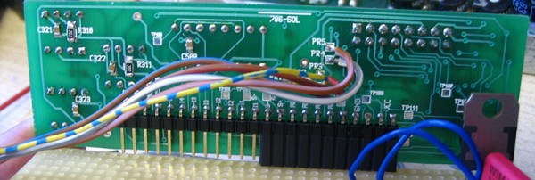
Everything lives on a PCB that fits right on the back of the instrument. Sadly, the connector needed to mate up to the one on the instrument was outlandishly expensive — again, avionics — so [porkfreezer] had to solder the board directly to the DME’s pins. Otherwise, this would have been a completely reversible hack.

Still, it’s an interesting reuse of an unusual piece of gear, and one that respects the original design as much as possible. That counts as a win in our book.

Modified Microwave Cures Resin Parts With Style

Once you make the leap to resin-based 3D printing, you’ll quickly find that putting parts out in the sun to cure isn’t always a viable solution. The best way to get consistent results is with a dedicated curing chamber that not only rotates the parts so they’re evenly exposed to the light, but allows you to dial in a specific curing time. A beeper that goes off when the part is done would be handy as well. Wait, this is starting to sound kind of familiar…

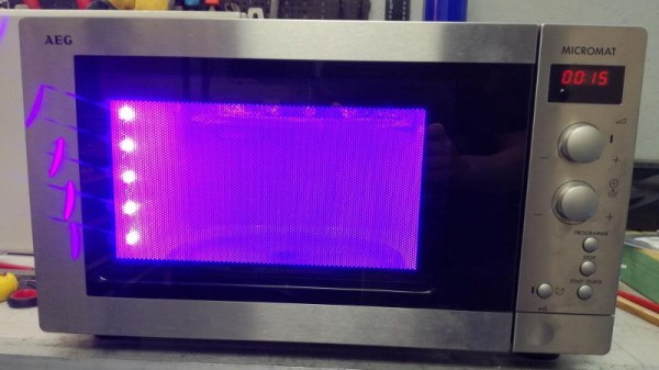
As you might expect, [Stynus] isn’t the first person to notice the similarities between an ideal UV curing machine and the lowly microwave oven. But his conversion is certainly one of the slickest we’ve ever seen. The final product doesn’t look like a hacked microwave so much as a purpose-built curing machine, thanks in large part to the fact that all of the original controls are still functional.

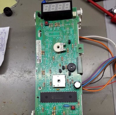
The big break there came when [Stynus] noticed that the control panel was powered by a one-time programmable PIC16C65B microcontroller. Swapping that out for the pin-compatible PIC16F877A opened up the possibility of writing custom firmware to interface with all the microwave’s original hardware, he just needed to reverse engineer how it was all wired up. It took some time to figure out how the limited pins on the microcontroller ran the LED display and read the buttons and switches at the same time, but we’d say the final result is more than worth the work.

With full control over the microwave’s hardware, all [Stynus] had to do was strip out all the scary high voltage bits (which were no longer functional to begin with) and install an array of UV LEDs. Now he can just toss a part on the plate, spin the dial to the desired curing time, and press a button. In the video below, you can see he’s even repurposed some of the buttons on the control panel to let him do things like set a new default “cook” time to EEPROM.

Compared to the more traditional fused deposition modeling (FDM) 3D printers, resin printing requires a lot of additional post-processing and equipment. You don’t necessarily have to gut your microwave just to cure your prints, but you’d be wise to fully consider your workflow will look like before pulling the trigger on that shiny new printer.

Continue reading “Modified Microwave Cures Resin Parts With Style”

Use Your Earbud’s Media Controls On Your Laptop With This Useful Dongle

[David] sends in his very nicely designed “Thumpware Media Controller” that lets your mobile phone headphones control the media playback on your PC.

We realize that some PCs have support for the extra pins on cellphone earbuds, but at least some of us have experienced the frustration (however small) of habitually reaching up to touch the media controls on our earbuds only to hear the forlorn click of an inactive-button. This solves that, assuming you’re still holding on to those 3.5mm headphones, at least.

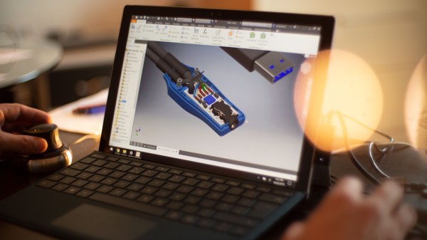
The media controls are intercepted by a PIC16 and a small board splits and interprets the signals into a male 3.5mm and a USB port. What really impressed us is the professional-looking design and enclosure. A lot of care was taken to plan out the wiring, assembly, and strain relief. Overall it’s a pleasure to look at.

All the files are available, so with a bit of soldering, hacking, and careful sanding someone could put together a professional looking dongle for their own set-up.

Generating Video With The PIC

[bekeband] recently came across an old industrial monitor. It’s small, monochrome, has a beautiful green phosphor, and does not accept a composite signal. Instead, there’s a weird TTL input with connectors for horizontal sync, vertical sync, and video. Intrigued, [bekeband] brought it home and started working on a project that would drive this monitor. He succeeded, and with a chip we don’t see much of on the Hackaday tips line: a 16-bit PIC.

The project uses the dsPIC30F3011, a strange little 16-bit PIC in a 40-pin package. The board for this build actually comes from an earlier build, and after connecting the horizontal sync, vertical sync, and video to this tiny board, [bekeband] started writing some code.

There are two programs written for this board. The first is a static image tester that displays a single image on the CRT. The second is one that displays a simple animation, in this case, a horse running in place. It’s not the fanciest project, but it does work, and even though [bekeband] isn’t using a high-speed ARM, he is getting a reasonably high resolution out of this chip.

Video below.

Continue reading “Generating Video With The PIC”

Super Serious Garage Door Opener

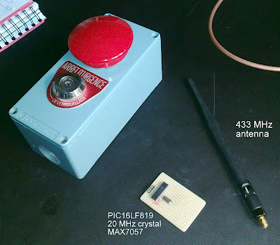
Tired of cheap plastic garage door openers? [Yetifrisstlama]’s is probably the most serious garage door opener that we’ve seen. The case is an old emergency stop switch, which has plenty of space for the circuitry and features a big red button.

This build log starts with details on reverse engineering the original door opener’s protocol. It’s an amplitude-shift keying (ASK) signal that sends a 10 bit code to authenticate. The main components inside are a PIC16LF819 microcontroller, a MAX7057 ASK/FSK transmitter, and some RF circuitry needed to filter the signal. There’s a mix of through hole and surface mount components mounted on a prototyping board, requiring some crafty soldering.

[Yetifrisstlama] says that the next step is to add a power amplifier to increase the range. The code and project files are also provided for anyone interested in working with ASK. While the hack looks awesome, it might make bystanders think you’re doing something more sinister than opening a garage door.

Adding A Keypad To A Key Card Lock

keypad

[Colin Merkel] had a little problem: he was continually forgetting his electronic key card, locking himself out of his own dorm room. Like any normal Hack a Day reader, rather than getting in the habit of always carrying his card, the natural impulse of course is to build this elaborate rig of electronics and duct tape. Right?

The result is an additional keypad that can be used to gain access…not by altering the existing electronic lock, but with a secondary mechanism that operates the inside door handle. An 8-bit PIC microcontroller scans the outside keypad (connected by a thin ribbon cable), and when a correct access code is entered, engages a 12 volt DC motor to turn the handle. It’s a great little writeup that includes a parts list, source code, and explains the process of keypad scanning.

It’s similar to the RFID-based dorm hack we previously posted. By physically operating the handle, most any approach could be used: facial recognition, other biometrics, DDR pad, or whatever inspired lunacy you can dream up.