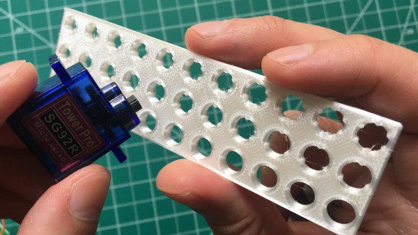
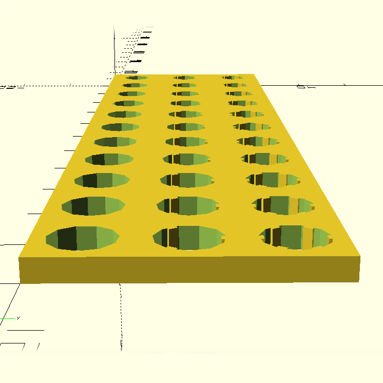
The Machinists’ Mantra: Precision, Thy Name Is Rigidity

“Everything is a spring”. You’ve probably heard that expression before. How deep do you think your appreciation of that particular turn of phrase really is? You know who truly, viscerally groks this? Machinists.

As I’ve blathered on about at length previously, machine tools are all about precision. That’s easy to say, but where does precision really come from? In a word, rigidity. Machine tools do a seemingly magical thing. They remove quantities of steel (or other materials medieval humans would have killed for) with a slightly tougher piece of steel. The way they manage to do this is by applying the cutting tool to the material within a setup that is so rigid that the material has no choice but to yield. Furthermore, this cutting action is extremely precise because the tool moves as little as possible while doing so. It all comes down to rigidity. Let’s look at a basic turning setup.

Continue reading “The Machinists’ Mantra: Precision, Thy Name Is Rigidity”

Precision Pantograph Probes PCBs

Electronic components are getting smaller and for most of us, our eyesight is getting worse. When [Kurt] started using a microscope to get a better view of his work, he realized he needed another tool to give his hands the same kind of precision. That tool didn’t exist so he built it.

The PantoProbe is a pantograph mechanism meant to guide a probe for reaching the tiny pads of his SMT components. He reports that he has no longer has any trouble differentiating pins 0.5 mm apart which is the diameter of the graphite sticks in our favorite mechanical pencils.

[Kurt] has already expanded his machine’s capability to include a holder for a high-frequency probe and even pulleys for a pick-and-place variation. There’s no mention of dual-wielding PantoProbes as micro-helping-hands but the versatility we’ve seen suggests that it is only a matter of time.

Four bar linkages are capable of some incredible feats and they’re found all around us. Enjoy one of [Kurt]’s other custom PCBs in his Plexitube Owl Clock, or let him show you to make 3D objects with a laser engraver.

Continue reading “Precision Pantograph Probes PCBs”

Hackaday Trims Its Own Resistors

There are times when you might want an odd-value resistor. Rather than run out to the store to buy a 3,140 Ω resistor, you can get there with a good ohmmeter and a willingness to solder things in series and parallel. But when you want a precise resistor value, and you want many of them, Frankensteining many resistors together over and over is a poor solution.

Something like an 8-bit R-2R resistor-ladder DAC, for instance, requires seventeen resistors of two values in better than 0.4% precision. That’s just not something I have on hand, and the series/parallel approach will get tiresome fast.

Ages ago, I had read about trimming resistors by hand, but had assumed that it was the domain of the madman. On the other hand, this is Hackaday; I had some time and a file. Could I trim and match resistors to within half a percent? Read on to find out.

Continue reading “Hackaday Trims Its Own Resistors”

Moving Microns With A High Precision Linear Stage

As anyone who has experimented with their own home-made CNC machinery will tell you, precision isn’t cheap. You can assemble a gantry mill using off-the-shelf threading and kitchen drawer slides. But it’s a safe assumption that if you put the tool at a particular position it won’t be quite at the same position next time you return. But if you take your budget from dirt cheap to reasonably priced you can do much better. [Adam Bender] designs high-precision automation systems for a living, so when he needed a precision linear stage for a personal project he achieved micron level accuracy for under $500.

micron-precision-linear-actuator
Red parts are the two spring-loaded nuts

He explains the problem of backlash with an inexpensive lead screw — the wiggle between threaded components that cause positional chaos. His solution uses two nuts preloaded against each other with a spring. There is still a stick-slip issue; a tendency to move in lurches due to differences between the coefficients of static and dynamic friction between the materials. Careful choice of machining stock for the nut to picking materials in which these coefficients were almost identical reduced the stick-slip to as little as possible.

He goes into significant detail on the design, manufacture, and testing of all the components of his stage, its body, sealing system, and control. If you are a precision CNC guru maybe you’ll find it interesting as a cleverly designed component, but if you are a mere dilettante you’ll find it fascinating to read a comprehensive but accessible write-up from a professional in the field.

This build probably goes a step beyond most we’ve featured in the past, but that’s not to say we’ve not seen some pretty good efforts.

Shop Made Squareness Comparator

[Stefan Gotteswinter] has a thing for precision. So it was no surprise when he confessed frustration that he was unable to check the squareness of the things he made in his shop to the degree his heart desired.

He was looking enviously at the squareness comparator that [Tom Lipton] had made when somone on Instagram posted a photo of the comparator they use every day. [Stefan] loved the design and set out to build one of his own. He copied it shamelessly, made a set of drawings, and got to work.

[Stefan]’s videos are always a trove of good machine shop habits and skills. He always shows how being careful, patient, and doing things the right way can result in really astoundingly precise work out of a home machine shop. The workmanship is beautiful and his knack for machining is apparent throughout. We chuckled at one section where he informed the viewer that you could break a tap on the mill when tapping under power if you bottom out. To avoid this he stopped at a distance he felt was safe: 0.5 mm away.

The construction and finishing complete, [Stefan] shows how to use the comparator at the end of the video, viewable after the break.

Continue reading “Shop Made Squareness Comparator”

3D Printer Tool: Set Your Extruder Steps With Ease

My printer has other issues that i'm still tuning out, but the warping in PLA and excessive surface roughness has all the signs of over extrusion.
My printer has other issues that I’m still tuning out, but the warping in PLA and excessive surface roughness has all the signs of over extrusion.

I have an old Prusa i2 that, like an old car, has been getting some major part replacements lately after many many hours of service. Recently both the extruder and the extruder motor died. The extruder died of brass fill filament sintering to the inside of the nozzle (always flush your extruder of exotic filaments). The motor died at the wires of constant flexing. Regardless, I replaced the motors and found myself with an issue; the new motor and hotend (junk motor from the junk bin, and an E3D v6, which is fantastic) worked way better and was pushing out too much filament.

The hotend, driver gear, extruder mechanics, back pressure, motor, and plastic type all work together to set how much plastic you can push through the nozzle at once. Even the speed at which the plastic is going through the nozzle can change how much friction that plastic experiences. Most of these effects are somewhat negligible. The printer does, however, have a sort of baseline steps per mm of plastic you can set.

The goal is to have a steps per mm that is exactly matched to how much plastic the printer pushes out. If you say 10mm, 10mm of filament should be eaten by the extruder. This setting is the “steps per mm” in the firmware configuration. This number should be close to perfect. Once it is, you can tune it by setting the “extrusion multiplier” setting in most slicers when you switch materials, or have environmental differences to compensate for.

This little guy lets you tune the steps per mm exactly.

The problem comes in measuring the filament that is extruded. Filament comes off a spool and is pulled through an imprecisely held nozzle in an imprecisely made extruder assembly. On top of all that, the filament twists and curves. This makes it difficult to hold against a ruler or caliper and get a trustworthy measurement.

I have come up with a little measuring device you can make with some brass tubing, sandpaper, a saw (or pipe cutter), a pencil torch, solder, and some calipers. To start with, find two pieces of tubing. The first’s ID must fit closely with the filament size you use. The second tube must allow the inside tubing to slide inside of it closely. A close fit is essential.

Continue reading “3D Printer Tool: Set Your Extruder Steps With Ease”