Peek At The Off-Ear Speaker Prototypes For Valve’s VR

The Valve Index VR headset incorporates a number of innovations, one of which is the distinctive off-ear speakers instead of headphones or earbuds. [Emily Ridgway] of Valve shared the design and evolution of this unusual system in a deep dive into the elements of the Index headset. [Emily] explains exactly what they were trying to achieve, how they determined what was and wasn’t important to deliver good sound in a VR environment, and what they were able to accomplish.

First prototype, a proof-of-concept that validated the basic idea and benefits of off-ear audio delivery.

Early research showed that audio was extremely important to providing a person with a good sense of immersion in a VR environment, but delivering a VR-optimized audio experience involved quite a few interesting problems that were not solved with the usual solutions of headphones or earbuds. Headphones and earbuds are optimized to deliver music and entertainment sounds, and it turns out that these aren’t quite up to delivering on everything Valve determined was important in VR.

The human brain is extremely good at using subtle cues to determine whether sounds are “real” or not, and all kinds of details come into play. For example, one’s ear shape, head shape, and facial geometry all add a specific tonal signature to incoming sounds that the brain expects to encounter. It not only helps to localize sounds, but the brain uses their presence (or absence) in deciding how “real” sounds are. Using ear buds to deliver sound directly into ear canals bypasses much of this, and the brain more readily treats such sounds as “not real” or even seeming to come from within one’s head, even if the sound itself — such as footsteps behind one’s back — is physically simulated with a high degree of accuracy. This and other issues were the focus of multiple prototypes and plenty of testing. Interestingly, good audio for VR is not all about being as natural as possible. For example, low frequencies do not occur very often in nature, but good bass is critical to delivering a sense of scale and impact, and plucking emotional strings.

“Hummingbird” prototype using BMR drivers. Over twenty were made and lent to colleagues to test at home. No one wanted to give them back.

The first prototype demonstrated the value of testing a concept as early as possible, and it wasn’t anything fancy. Two small speakers mounted on a skateboard helmet validated the idea of off-ear audio delivery. It wasn’t perfect: the speakers were too heavy, too big, too sensitive to variation in placement, and had poor bass response. But the results were positive enough to warrant more work.

In the end, what ended up in the Index headset is a system that leans heavily on Balanced Mode Radiator (BMR) speaker design. Cambridge Audio has a short and sweet description of how BMR works; it can be thought of as a hybrid between a traditional pistonic speaker drivers and flat-panel speakers, and the final design was able to deliver on all the truly important parts of delivering immersive VR audio in a room-scale environment.

As anyone familiar with engineering and design knows, everything is a tradeoff, and that fact is probably most apparent in cutting-edge technologies. For example, when Valve did a deep dive into field of view (FOV) in head-mounted displays, we saw just how complex balancing different features and tradeoffs could be.

Rapid Prototyping System Gives Wheels To Wearables

Wearables are kind of a perplexing frontier for electronics. On the one hand, it’s the best possible platform for showing off a circuit everywhere you go. On the other hand, the whole endeavor is fiddly because the human body has no straight lines and moves around quite a bit. Circuits need to be flexible and comfortable. In other words, a wearable has to be bearable.

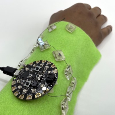
[Konstantin], [Raimund], and [Jürgen] have developed an intriguing system for prototyping e-textiles that opens up the wearables world to those who don’t sew and makes the prototyping process way easier for everyone.

It’s a small and portable roll-on ironing device that lays down different kinds of custom ‘tapes’ on to textiles. The conductive fabric tapes can be used as touchable traces, and can support components such as flexible e-ink screens and solar panels. Some tapes provide single or multiple points of connectivity, and others are helper substrates like polyimide tape that multiply the possibilities for complex circuits.

The device uses a modified soldering iron to transfer the tapes, which are loaded onto 3D-printed spools that double as the wheels. Check it out after the break — there’s a 30-second tour and a 5-minute exploration of the whole process.

Everyone needs to prototype, even the seasoned stitchers. The next time you’re thinking in thread, throw some magnets into the process.

Continue reading “Rapid Prototyping System Gives Wheels To Wearables”

An Adapter To Solve Your ESP-01 Breadboard Woes

The ESP-01 launched the ESP8266 revolution back in 2014, and while today you’re far more likely to see somebody use a later version of the chip in a Wemos or NodeMCU development board, there are still tasks the original chip is well suited for. Unfortunately, they can be tricky to use while prototyping because they aren’t very breadboard friendly, but this adapter developed by [Miguel Reis] can help.

Of course, the main issue is the somewhat unusual pinout of the ESP-01. Since it was designed as a daughter board to plug into another device, the header is too tight to fit into a breadboard. The adapter that [Miguel] has come up with widens that up to the point you can put it down the centerline of your breadboard and have plenty of real estate around it.

The second issue is that the ESP-01 is a 3.3 V device, which can be annoying if everything else in the circuit is running on 5 V. To get around this, the adapter includes an SPX3819 regulator and enough capacitors that the somewhat temperamental chip gets the steady low-voltage supply it needs to be happy.

[Miguel] has released the schematics and board files so you can spin up your own copy of the adapter, but they’re also available for around $3 USD from his Tindie store.

Don’t Scrape Magnet Wire, Do This Instead

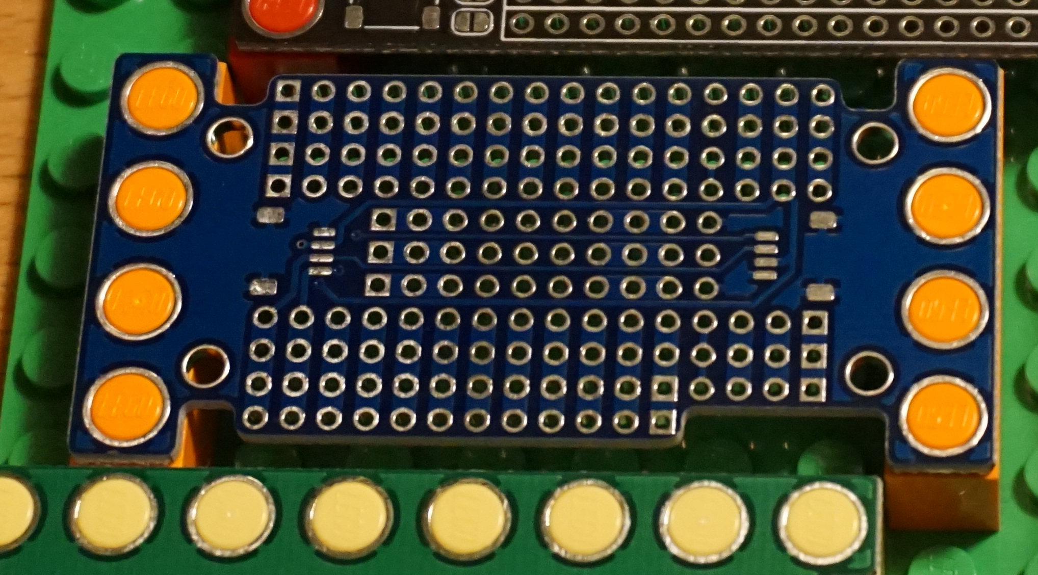
[Tom] doesn’t much like breadboarding. He prefers to wire up prototypes with perfboard and solder point-to-point with enameled magnet wire. That may sound troublesome to some of you, but [Tom] has come up with a few tips to make prototyping with perfboard and magnet wire easier and more effective, and the biggest tip is about how to manage stripping all that magnet wire.

Push the tip of the magnet wire a small distance into the molten solder and hold it there for a few moments. The solder will bubble away the enamel and tin the copper underneath in the process.

Magnet wire is a thin, solid-core conductor that has a clear coating of enamel. This enamel acts as an electrical insulator. The usual way to strip away the enamel and reveal the shiny copper underneath is to scrape it off, but that would get tiresome when working with a lot of connections. [Tom] prefers to “boil it away” with a blob of molten solder on an iron’s tip.

Begin by melting a small amount of solder on the iron, then push the tip of the magnet wire a small distance into the molten solder and hold it there for a few moments. The enamel will bubble away and the solder will tin the copper underneath in the process. The trick is to use fresh solder, and to clean the tip in between applications. You can see him demonstrate this around the 1:00 mark in the video embedded below.

Once the tip of the magnet wire is tinned, it can be soldered as needed. Magnet wire bends well and holds its shape nicely, so routing it and cutting to size isn’t too difficult. [Tom] also suggests a good hands-free PCB holder, and points out that 0603 sized SMT resistors fit nicely between a perfboard’s 0.1″ pads.

Perfboard (and veroboard) have been standbys of prototyping for a long time, but there are still attempts at improving them, usually by allowing one to combine through-hole and surface-mount devices on the same board, but you can see [Tom] demonstrate using magnet wire on plain old perfboard in the video below.

Continue reading “Don’t Scrape Magnet Wire, Do This Instead”

Magnets Make Prototyping E-Textiles A Snap

How do you prototype e-textiles? Any way you can that doesn’t drive you insane or waste precious conductive thread. We can’t imagine an easier way to breadboard wearables than this appropriately-named ThreadBoard.

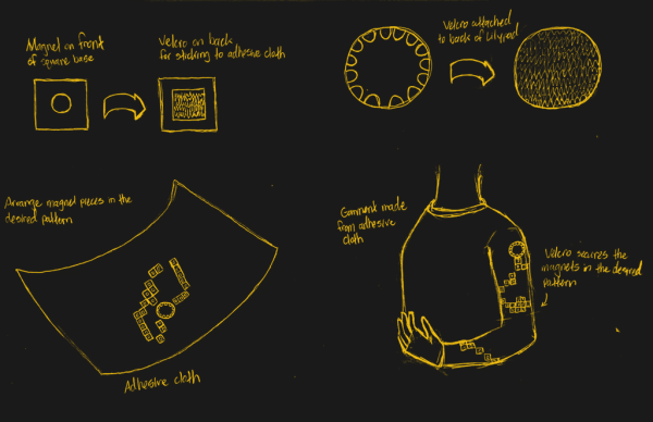
If you’ve never played around with e-textiles, they can be quite fiddly to prototype. Of course, copper wires are floppy too, but at least they will take a shape if you bend them. Conductive thread just wants lay there, limp and unfurled, mocking your frazzled state with its frizzed ends. The magic of ThreadBoard is in the field of magnetic tie points that snap the threads into place wherever you drape them.

The board itself is made of stiff felt, and the holes can be laser-cut or punched to fit your disc magnets. These attractive tie-points are held in place with duct tape on the back side of the felt, though classic double-stick tape would work, too. We would love to see somebody make a much bigger board with power and ground rails, or even make a wearable ThreadBoard on a shirt.

Even though [chrishillcs] is demonstrating with a micro:bit, any big-holed board should work, and he plans to expand in the future. For now, bury the needle and power past the break to watch [chris] build a circuit and light an LED faster than you can say neodymium.

The fiddly fun of e-textiles doesn’t end with prototyping — implementing the final product is arguably much harder. If you need absolutely parallel lines without a lot of hassle, put a cording foot on your sewing machine.

Continue reading “Magnets Make Prototyping E-Textiles A Snap”

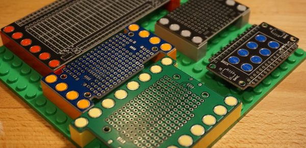
3D Printed Breadboard Helper Makes Wiring Neater And Easier

Breadboards make it simple to prototype and test circuits. If you use flexible wires with pins to make connections, it usually results in a rat’s nest. For many of us, using solid wire makes a rat’s nest, too. However, the very neat among us will cut solid wire to just the right length and strip just the right amount of wire and lay the wires very flat and neat along the board. [Moononournation] did a 3D print that makes the latter method much easier. You can find his Breadboard Wire Helper on Thingiverse and see a video, below.

The idea is simple: start with a piece of wire stripped on one side, then count out the number of holes it needs to traverse and push the stripped end through the hole. Trim the wire to fit. To complete the other side, lay the wire flat along the tool to the edge. Now you can see where to strip that side of the wire. After you remove the insulation, you can bend the wire down and cut the wire to fit. Now you have a perfect size and shape wire to place in the actual breadboard.

Granted, this isn’t that hard to do with the existing breadboard if it isn’t too packed. You could even use a spare breadboard. But it is a little easier to trim the wire to the right size with this jig. If you don’t want to 3D print it, you could probably pull the tape off the back of a cheap board and remove the springs to get a similar effect.

So while this little tool probably won’t change your life, it might make it a little easier. What other tools do you use when breadboarding? Let everyone know in the comments.

Continue reading “3D Printed Breadboard Helper Makes Wiring Neater And Easier”

New Part Day: The Wi-Fi Stepper Gets Ideas Working Faster

Like most of us, I sometimes indulge in buying a part for its potential or anticipated utility rather than for a specific project or purpose. That’s exactly how I ended up with the WSX100 Wi-Fi Stepper, a single board device intended to be one of the fastest and easiest ways to get a stepper motor integrated into a project. Mine came from their Crowd Supply campaign, which raised money for production and continues to accept orders.

What’s It For?

The WSX100 Wi-Fi Stepper Driver (with motor), by Good Robotics

The main reason the Wi-Fi Stepper exists is to make getting a stepper motor up and running fast and simple, in a way that doesn’t paint a design into a corner. The device can certainly be used outside of prototyping, but I think one of its best features is the ability to help quickly turn an idea into something physical. When prototyping, it’s always better to spend less time on basic bits like driving motors.

In a way, stepper motors are a bit like RGB LEDs or LCD displays were before integrated drivers and easy interfaces became common for them. Steppers require work (and suitable power supplies) to get up and running, and that effort can be a barrier to getting an idea off the ground. With the Wi-Fi Stepper, a motor can be fired up and given positional commands (or set to a speed and direction) in no time at all. By sending commands over WiFi, there isn’t even the need to wire up any control logic.

Continue reading “New Part Day: The Wi-Fi Stepper Gets Ideas Working Faster”