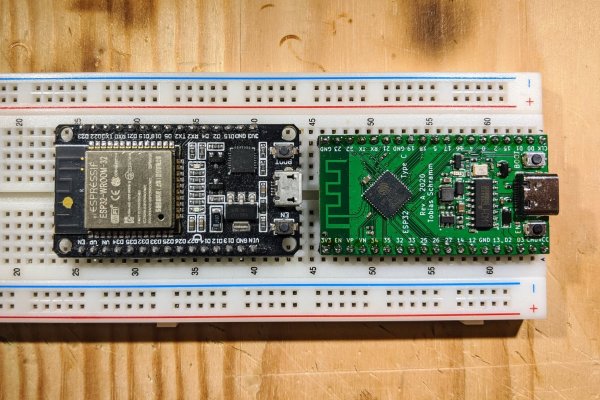
Sometimes the most useful hacks aren’t the flashiest, they’re the ones that improve an already great tool and make something better. Through hole components are still the fastest and perhaps most satisfying way to prototype a new electronics project so it’s extra frustrating when the happy hacker discovers their new devboard is too wide to fit in a standard breadboard. [Tobias] had the same thought and redesigned the standard ESP32 “NodeMCU” style devboard to be almost exactly the same, but narrower.
Not to trivialize, but that’s pretty much it. And we love it! The new design retains the great support of the original devboard but adds a few nice tweaks. Obviously there’s the small size change that allows it to fit on a standard 5×5 breadboard leaving sockets available on either side for interfacing. Even in this smaller size [Tobias] managed to retain the boot mode and reset buttons though the overall pinout has changed slightly. And for easier connections ye olde micro USB socket has been swapped for sleek modern USB-C. You have cables for that common standard now, right?
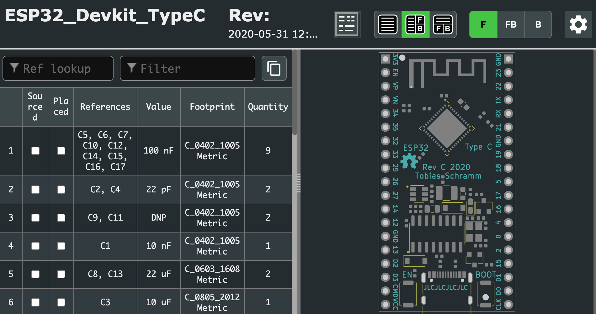
How do you get one? As far as we know [Tobias] isn’t selling these but the design is completely open source and the design, fab, and BOM files are all in the github repository. [Tobias] even went so far as to include the extremely handy interactive BOM to speed up hand assembly. The real trick here is that the board is designed to facilitate the extremely inexpensive turnkey assembly now available from our favorite fab houses, with an example cost of $8/piece for a run of five. The repo includes a properly formatted BOM and fab files to make ordering them a snap. See the bottom of the README for details about what to order.