Spying On The ESP32’s GPIO

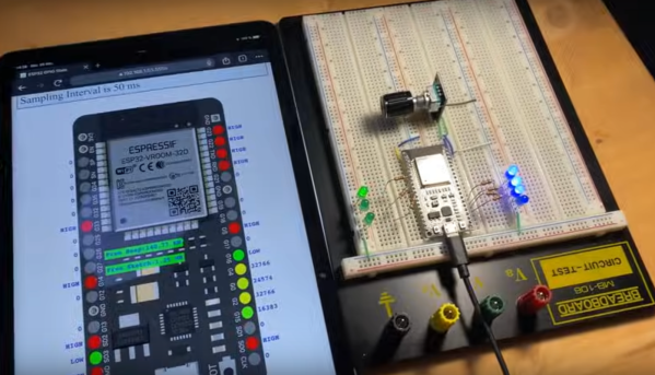
The ESP32 has been a go-to microcontroller platform for a while now, thanks to its versatile capabilities, integrated Wi-Fi and Bluetooth connectivity, and low power consumption. It’s ideal for a wide range of projects especially those revolving around IoT, partially because of all of the libraries and tools available for it now. The latest tool from [The Last Outpost Workshop] adds a feature we didn’t know we wanted until now: a webserver showing real-time updates of what all of the GPIO pins are doing.

The live GPIO pin monitoring library sets up the ESP32 to stream information about what all of the pins are doing in real time to a webserver, which displays the information as a helpful graphic. The demonstration in the video below shows and example troubleshooting a situation where the code is correct but there’s a mistake in the wiring, helping to quickly identify the problem and hopefully eliminating a wild goose chase for a bug in the software. The library can be quickly installed using the Arduino IDE and only requires the use of one other library and a few lines of code to get everything up and running.

As far as a debugging tool goes, something like this could save a lot of us a significant amount of time, especially with how easy it is to set up. A real-time look into the pins and their behavior, including those set up for PWM, is invaluable for plenty of situations. Of course if you’re building something like a real-time operating system that needs responses within a very specific interval you may want to look at more in-depth strategies for probing the GPIO.

Thanks to [Bob] for the tip!

Continue reading “Spying On The ESP32’s GPIO”

Bigfoot Turns Classic Sewing Machine Into A Leather-Eating Monster

If you try to sew leather on a standard consumer-grade machine, more often than not you’ll quickly learn its limits. Most machines are built for speed, and trying to get them to punch through heavy material at the low motor speeds often needed for leather work is a lesson in frustration.

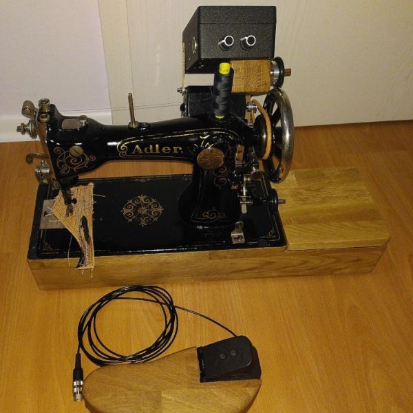
How frustrating? Enough so that [Joseph Eoff] expended considerable effort to create this sewing machine speed controller for his nearly century-old Adler sewing machine. The machine was once powered by a foot treadle, which is probably why the project is dubbed “Bigfoot,” but now uses a 230 V universal motor. Such motors don’t deliver much torque when run at low speeds with the standard foot-pedal rheostat control, so [Joseph] worked up an Arduino-based controller with a tachometer for feedback and a high-power PWM driver for the motor.

There are a ton of details in [Joseph]’s post and even more in the original blog article, which is well worth a read, but a couple really stand out. The first is with the tachometer, which uses an off-the-shelf photointerrupter and slotted disc. [Joseph] was displeased with the sensor’s asymmetrical and unreliable output, so he made some modifications to the onboard comparator to square up the signal. Also interesting is the PID loop auto-tuning function he programmed into Bigfoot; press a button and the controller automatically ramps the motor speed up and down and stores the coefficients in memory. Nice!

The short video below shows Bigfoot in action with varying thicknesses of faux leather; there are also some clips in the original article that show the machine dealing with a triple thickness of leather at slow speed and not even breaking a sweat. Hats off to [Joseph] on a solid build that keeps a classic machine in the game. And if you want to get into the textile arts but don’t know where to start, we’ve got you covered.

Continue reading “Bigfoot Turns Classic Sewing Machine Into A Leather-Eating Monster”

Simple Circuit Keeps Process Control Loops In Tune

Spare a moment’s pity for the process engineer, whose job it is to keep industrial automation running no matter what. These poor souls seem to be forever on call, fielding panicked requests to come to the factory floor whenever the line goes down. Day or night, weekends, vacations, whatever — when it breaks, the process engineer jumps.

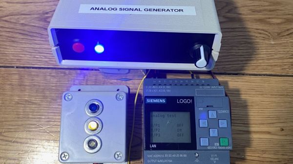
The pressures of such a gig can be enormous, and seem to have weighed on [Tom Goff] enough that he spent a weekend building a junk bin analog signal generator to replace a loop calibrator that he misplaced. Two process control signaling schemes were to be supported — the 0 to 10 VDC analog signal, and the venerable 4-20 mA current loop. All that’s needed for both outputs is an Arduino and an LM358 dual op-amp, plus a few support components. The 0-10 V signal starts as a PWM output from the Arduino, with its 0-5 V average amplified by one of the op-amps set up as a non-inverting amp with a gain of 2. With a little filtering, the voltage output is pretty stable, and swings nicely through the desired range — see the video below for that.

The current loop output is only slightly more complicated. An identical circuit on a separate Arduino output generates the same 10 V max output, but a code change limits the low end of the range to 1 V. This output of the op-amp is fed through a 500-Ω trimmer pot, and the magic of Ohm’s Law results in a 4-20 mA current. The circuit lives on a piece of perf board in a small enclosure and does the job it was built for — nothing fancy needed.

And spoiler alert: [Tom] found the missing loop calibrator — after he built this, of course. Isn’t that always the way?

Continue reading “Simple Circuit Keeps Process Control Loops In Tune”

Hackaday Prize 2023: 10 KW Electronic Load

[tinfever] needed a high-power benchtop electronic load for an upcoming project, and by their own admission decided foolishly to build their own. And we’re glad they did. The thing is, whilst this isn’t exactly a super-cheap project to build, buying a commercial offering with a capability of 10 kW and up to 30 kW pulsed, is going to cost an absolute fortune.

A selection of small resistors

Built inside a cubic frame using what appears to be standard 2020 aluminum rails and fixturing, the modular construction is nice and clean, with plenty of space around the load boards to allow the cooling air to circulate.

The operating principle is very simple; custom PCBs act in parallel to provide any load needed, by switching in the on-board load resistor. Each load board handles all the details of switching and dumping the power due to the inductance in the system wiring and the wire-wound resistors themselves.

Whilst we know that wire-wound resistors are reverse-wound to minimize inductance, there will still be some, and each load board will contribute a little more when the whole system is scaled up. Also, each load PCB handles its own temperature sensing, and current measurement passing these data off to the control PCB. A front-end connector PCB provides a variety of connection options to interface to the DUT (Device Under Test.) The system controller is based around an STM32 processor which deals with quite a lot more than you might think is needed on a first look.

The sense currents from each load need to be sensed, scaled, and summed to keep the overall load accuracy within the 1% spec. Also, it is on duty for PWM control of the cooling fans, handling the user interface, and any other remote connectivity. There are a lot of details on the project page, as we’re only skimming the surface here. If you’re interested in building an active load, this is a project you really should be digging into.

We shall watch with interest for when [tinfever] scales up this eight-slot prototype to the full specification of 52 stages! When working with power applications, there comes a point when you really need an electronic load, and to that end, here’s one with a very specific use case to get you started.

There is also the option of buying something cheap from the usual sources and hacking on some custom firmware to adapt it a little to your needs.


Accurate Cycle Counting On RP2040 MicroPython

The RP2040 is a gorgeous little chip with a well-defined datasheet and a fantastic price tag. Two SDKs are even offered: one based on C and the other MicroPython. More experienced MCU wranglers will likely reach for the C variant, but Python does bring a certain speed when banging out a quick project or proof of concept. Perhaps that’s why [Jeremy Bentham] ported his RP2040-based vehicle speedometer to MicroPython.

The two things that make that difficult are that MicroPython tries to be pretty generic, which means some hackery is needed to talk to the low-level hardware, and that MicroPython doesn’t have a reputation for accurate cycle counting. In this case, the low-level hardware is the PWM peripheral. He details the underlying mechanism in more detail in the C version. On the RP2040, the PWM module can count pulse edges on an input. However, you must start and stop it accurately to calculate the amount of time captured. From there, it’s just edges divided by time. For this, the DMA system is pulled in. A DMA request can be triggered once the PWM counter rolls over. The other PWM channel acts as a timer, and when the timer expires, the DMA request turns off the counter. This works great for fast signals but is inaccurate for slow signals (below 1kHz). So, a reciprocal or time-interval system is included, where the time between edges is captured instead of counting the number of edges in a period,

What’s interesting here is how the hardware details are wrapped neatly into pico_devices.py. The uctypes module from MicroPython allows access to MMIO devices such as DMA and PWM. The code is available on GitHub. Of course, [Jeremy] is no stranger to hacking around on the RP2040, as he has previously rolled his own WiFi driver for the Pico W.

Tesla Door Phone Decoded (Not That Tesla)

[Danman] has digital door phones manufactured by Tesla — or at least, a Tesla, as they’re not to be confused with the carmaker, though. The problem is if someone comes to the door when no one’s home, there’s no remote indicator. The answer? Reverse engineer the protocol and fix it.

A quick dump on a storage scope showed the data clearly, but it wasn’t obvious what protocol it was using. After a little analysis, it proved the datastream used 4 PWM pulses as symbols with three symbols: one, zero, and stuffing sequence.

Once you can read the bits, it is easy to determine that each frame consists of a 16-bit destination and source address, along with a command byte and a checksum byte. Each station can have an ID from 000 to 999 although you can only dial up to number 323. Some nodes are special, and there are ways to address particular units.

Connecting to the hardware took a transformer for isolation. Honestly, unless you have this exact hardware, this isn’t likely to be something you can directly use. However, it is a great example of how you can figure out a specialized device and bend it to your will.

We love reverse engineering projects. In some cases, it is easier if you have a CT scan.

Converting A B&W Enlarger For Colour Analog Photo Printing

[Koraks tinkers] was gifted a gargantuan photographic enlarger, a Durst Laborator 138 s, which is a unit designed specifically for black and white usage only. This was not good enough for [Koraks] so down the rabbit hole of conversion to colour we go! The moral of the story is this: if you can’t find it, build it. The hacker mentality. After wasting time and effort trying to source a period colour head for the thing, [Koraks] did the decent thing and converted what was already in front of them.

A hacked Chinese-sourced COB array. This is no use.

Now, if you’re thinking this process is simply a matter of ripping out the tungsten bulb and sticking a high-power RGB array in there, then you’re going to be disappointed! You see, colour photography of the era — specifically the RA4 process in this case — requires careful colour calibration and is heavily biased towards the red end of the visible spectrum, due to the colour curve of those tungsten bulbs we touched upon earlier.

Attempt 2: With a heavy bias towards the red end of the spectrum

The first attempt at using an off-the-shelf COB array was a bust — it simply wasn’t bright enough once the light had passed through the diffuser plate, and the light path losses were too high to expose the RA4 paper sufficiently, especially at the red end of the spectrum. Quite simply this is due to the reduced energy of red photons (compared to blue) making the desired chemical reaction rate too low. The solution is more power.

Another issue that quickly raised itself was that 8-bits of PWM control of the RGB components was inadequate since the ratio of blue to red required was so skewed, that only a few effective bits of blue channel control were usable, and that was far too granular to get the necessary accuracy.

[Koraks’] approach was to custom build an LED array with twenty red 3W LEDs and eight each of the green and blue devices. 12-bits of PWM resolution was delivered via a PCA9685 PWM controller, that also handily controlled the cooling fans. The whole thing was hooked up to an Arduino Nano, with an MCP23016 expander board performing the duty of interfacing the rotary encoders and trigger footswitch. In fact, several iterations of the LED array have been constructed and this four-part blog series (Part1, Part2, Part3, Part4) lays out the whole story in all its gory detail for your entertainment. Enjoy!

COB LED arrays are pretty nifty, checkout turning them into 7-segment displays, just because. If all you want is raw power, we reckon that 100W “should be enough for anyone…”

Thanks [macsimski] for the tip!

Update: Corrected the article header from ‘exposer head’ to ‘enlarger’ for clarity at the request of the project author.