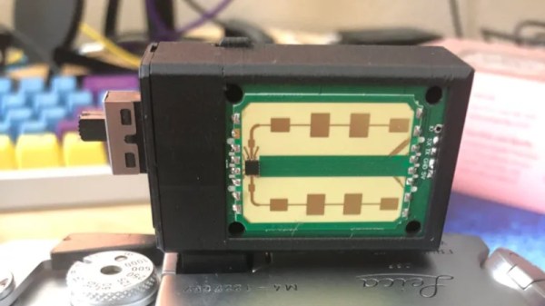
As the art of film photography has gained once more in popularity, some of the accessories from a previous age have been reinvented, as is the case with [tdsepsilon]’s radar rangefinder. Photographers who specialized in up-close-and-personal street photography in the mid-20th century faced the problem of how to focus their cameras. The first single-lens reflex cameras (SLRs) were rare and expensive beasts, so for most this meant a mechanical rangefinder either clipped to the accessory shoe, or if you were lucky, built into the camera.
The modern equivalent uses an inexpensive 24 GHz radar module coupled to an ESP32 board with an OLED display, and fits in a rather neat 3D printed enclosure that sits again in the accessory shoe. It has a 3 meter range perfect for the street photographer, and the distance can easily be read out and dialed in on the lens barrel.
Whenever the revival of film photography is discussed, it’s inevitable that someone will ask why, and point to the futility of using silver halides in a digital age. It’s projects like this one which answer that question, with second-hand SLRs being cheap and plentiful you might ask why use a manual rangefinder over one of them, but the answer lies in the fun of using one to get the perfect shot. Try it, you’ll enjoy it!
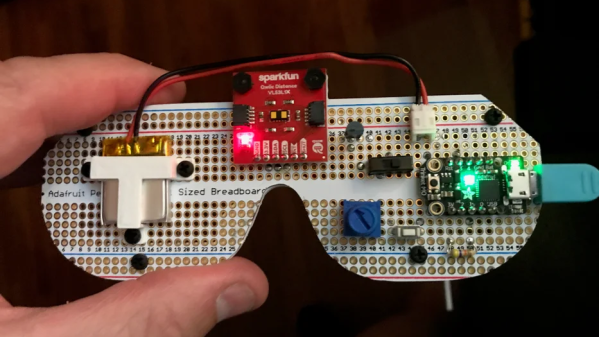
[tpsully]’s Radar Glasses are designed as a way of sensing the world without the benefits of normal vision. They consist of a distance sensor on the front and a vibration motor mounted to the bridge for haptic feedback. The little motor vibrates in proportion to the sensor’s readings, providing hands-free and intuitive feedback to the wearer. Inspired in part by his own experiences with temporary blindness, [tpsully] prototyped the glasses from an accessibility perspective.
The sensor is a VL53L1X time-of-flight sensor, a LiDAR sensor that measures distances with the help of pulsed laser light. The glasses do not actually use RADAR (which is radio-based), but the operation is in a sense quite similar.
The VL53L1X has a maximum range of up to 4 meters (roughly 13 feet) in a relatively narrow field of view. A user therefore scans their surroundings by sweeping their head across a desired area, feeling the vibration intensity change in response, and allowing them to build up a sort of mental depth map of the immediate area. This physical scanning resembles RADAR antenna sweeps, and serves essentially the same purpose.
There are some other projects with similar ideas, such as the wrist-mounted digital white cane and the hip-mounted Walk-Bot which integrates multiple angles of sensing, but something about the glasses form factor seems attractively intuitive.
Thanks to [Daniel] for the tip, and remember that if you have something you’d like to let us know about, the tips line is where you can do that.
When you’ve been a fact-sponge for electronics trivia for over four decades, it’s not often that an entire class of parts escapes your attention. But have you seen the Skiatron? It’s a CRT that looks like a normal mid-20th-century tube, until it’s switched on. Then its secret is revealed; instead of the glowing phosphor trace we’d expect, the paper-white screen displays a daylight-readable and persistent black trace. They’re invariably seen in videos of radar installations, with the 360 degree scans projected onto large table-top screens which show the action like a map. It’s like e-ink, but from the 1940s. What’s going on?
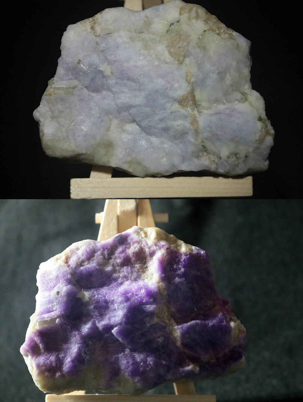
The tenebrescent mineral Hackmanite, before and after UV exposure. Leland Green…, CC BY-SA 2.0 and CC BY-SA 2.0.
The phosphor coating on a traditional CRT screen is replaced by a halide salt, and the property on which the display relies is called tenebrescence, changing colour under the influence of radiation. This seems most associated online with UV treatment of some minerals and gemstones to give them a prettier look, and its use a s a display technology is sadly forgotten.
A high-school physics understanding of the phenomenon is that energy from the UV light or the electron beam in the case of the tube, places some electrons in the crystal into higher energy levels, at which they absorb some visible light wavelengths. This is reversible through heat, in some substances requiring the application of heat while in others the heat of room temperature being enough. Of course here at Hackaday we’re hands-on people, so into the EPROM eraser went a small amount of table salt in a makeshift dish made of paper, but sadly not to be rewarded by a colour change.
On a real dark-trace CRT the dark trace would be illuminated from behind by a ring light round the glass neck of the tube. An interesting aside is that, unlike phosphor CRTs, they were more suitable for vertical mounting. It seems that small amounts of phosphor could detach themselves from a vertically mounted screen and drop into the electron gun, something that wasn’t a problem for tenebrescent coatings.
This display tech has shuffled off into the graveyard of obsolescence, we’re guessing because CRT technology became a lot better over the 1950s, and radar technologies moved towards a computerised future in which the persistence of the display wasn’t the only thing keeping the information on the screen. It seems at first sight to be a surprise that tenebrescent coatings have never resurfaced in other displays for their persistence, but perhaps there was always a better alternative whether it was ultra-low-power LCDs or more recently e-ink style devices.
For more bleeding-edge 1950s radar displays, we’ve previously brought you Volscan, a radar with an early form of GUI, which no doubt was one of those which consigned dark-trace CRTs to history.
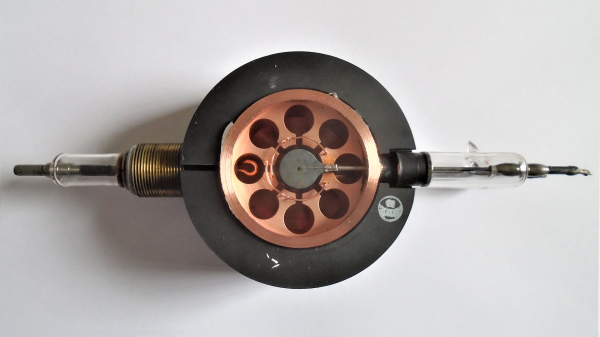
[Curious Droid] is back with a history lesson on one of the most important inventions of the 20th century: The cavity magnetron. Forged in the fighting of World War II, the cavity magnetron was the heart of radar signals used to identify attacking German forces.
The magnetron itself was truly an international effort, with scientists from many countries providing scientific advances. The real breakthrough came with the work of [John Randall] and [Harry Boot], who produced the first working prototype of a cavity magnetron. The device was different than the patented klystron, or even earlier magnetron designs. The cavity magnetron uses physical cavities and a magnetic field to create microwave energy. The frequency is determined by the size and shape of the cavities.
While the cavity magnetron had been proven to work, England was strapped by the war effort and did not have the resources to continue the work. [Henry Tizzard] brought the last prototype to the USA where it was described as “the most valuable cargo ever brought to our shores”. The cavity magnetron went on to be used throughout the war in RADAR systems both air and sea.
Today, many military RADAR systems use klystrons or traveling wave tube amplifiers due to requirements for accurate frequency pulses. But the cavity magnetron still can be found in general and commercial aviation RADAR systems, as well as the microwave ovens we all know and love.
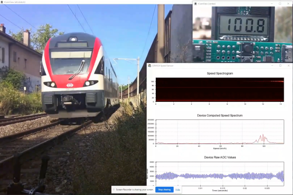
Some people hate to revisit projects that are done and dusted. We get that; it’s a little like reading a book you’ve already read when there are so many others to choose from. But rereading a book sometimes reveals subtle nuances you missed the first time around, and revisiting projects can be much the same, as with this new and improved Doppler radar speed sensor.
We seem to have been remiss in writing up [Limpkin]’s last go-around with the CDM324 microwave module, a 24-GHz transceiver that you can pick up on the cheap from the usual sources, but we’ve featured this handy little module in plenty of other projects. [Limpkin]’s current project uses the same module to create a Doppler speed sensor, but with a little more sophistication all around. Whereas the original used a simple comparator to output a square wave that’s proportional to the Doppler shift and displayed the speed on a simple terminal session, version two takes a different tack.
First, [Limpkin] opted to implement the whole sensor in hardware. The front end is quite different — an op-amp with 84 dB of gain followed by an automatic gain control (AGC) stage built from a MAX9814 microphone preamp. Extraction of the speed from the module output is left to an STM32F301 running an FFT algorithm on the signal coming out of the analog circuit, which essentially picks out the biggest peak in the spectrum and calculates the Doppler shift from that, displaying the results on an LCD display.
Of course, as a [Limpkin] project, there’s a lot more to it than just that. The write-up is very detailed, going down a few enjoyable rabbit holes like characterizing the amplification chain and diving into the details of Johnson-Nyquist noise to chase down stray oscillations. There’s some great stuff here, and it’s well worth a deep read; there’s also the video below that lets you see (and hear) what’s going on.
Having a computer that locks its screen after a few minutes of inactivity is always a good idea from a security standpoint, especially in offices where there is a lot of foot traffic. Even the five- or ten-minute activity timers that are set on most workstations aren’t really perfect solutions. While ideally in these situations we’d all be locking our screens manually when we get up, that doesn’t always happen. The only way to guarantee that this problem is solved is to use something like this automatic workstation locker.
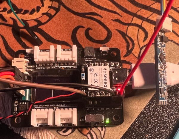
The project is based around the LD2410 presence sensor — a small 24 GHz radar module featuring onboard signal processing which simplifies the detection of objects and motion. [Enzo] paired one of these modules with a Seeed Studio XIAO nRF52840 development board to listen to the radar module and send the screen lock keyboard shortcut to the computer when it detects that the user has walked away from the machine. The only thing that [Enzo] wants to add is a blinking LED to let the user know when the device is about to timeout so that it doesn’t accidentally lock the machine when not needed.
One of the parts of this build that is a little bit glossed over is the fact that plenty of microcontroller platforms can send keystrokes to a computer even if they’re not themselves a USB keyboard. Even the Arduino Uno can do this, so by now this feature is fairly platform-agnostic. Still, you can use this to your advantage if you have the opposite problem from [Enzo] and need your computer to stay logged in no matter what.
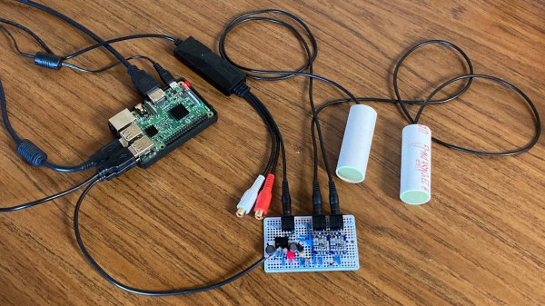
One of the most common ways of measuring the speed of a vehicle is by using radar, which typically involves generating radio waves, directing them at a moving vehicle, and measuring the various ways that they return to the device. This is a tried-and-true method, but can be expensive and technically complex. [GeeDub] wanted an easier way of measuring vehicles passing by his home, so he switched to using sonar instead to measure speeds based on the sounds the cars generate themselves.
The method he is using is similar to passive sonar in submarines, which can locate objects underwater based on the sounds they produce. After a false start attempting to measure Doppler shift, he switched to time correlation using two microphones, essentially using stereo audio input to detect subtle differences in arrival times of various sounds to detect the positions of passing vehicles. Doing this fast enough and extrapolating the data gathered, speed information can be calculated. For the data gathering and calculation, [GeeDub] is using a Raspberry Pi to help keep costs down, and some further configuration of the microphones and their power supplies were also needed to ensure quality audio was gathered.
With the system in place in a window, it detected around 9,000 vehicles over a three-day period. The software generates a normal distribution of vehicle speeds for this time, with the distribution centered on around 35 MPH, slightly above the posted speed limit of 30. As long as there’s a clear line of sight to the road using this system it’s just as effective as some other passive systems we’ve seen to measure vehicle speed. Of course, active speed measurement systems are not out of the realm of possibility if you’re willing to spend a little more.