Before the introduction of the Raspberry Pi, building robots was hard. The best solution to turning motors on a chassis was repurposing an old roomba. For the brain, maybe you could throw Linux on a router and move your rover around with an old Linksys. Before that, you could buy a crappy robotics kit, thrown together in a box and sold as an ‘educational kit’. I’m sure there are a few readers out there that built robots by wire-wrapping HC11s.
Now we have 3D printers and Raspberry Pis, and with that comes a golden age of robotics. One of the best robot brains out there is the 8BitRobots Modules from [Tim Wilkinson], an entry for this year’s Hackaday Prize.
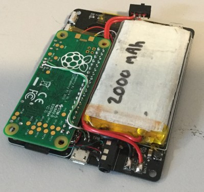
The 8BitRobots Modules are made up of a few components, not the least of which is a Pi Zero, a fantastically powerful (for its price) Linux computer that is available for five dollars. With an add-on board, cleverly named the RoBonnet, the Pi Zero gets PWM outputs for servos and ESCs, an H-bridge for motors, TTL serial, encoder inputs, a pressure and temperature sensor, an IMU, a power monitor, and everything else you need for a successful Pi robot.
But hardware is only one part of the equation. If you want to program a robot, you need a software stack that makes everything easy. That’s where the 8BitRobots distributed robot platform comes in. This is a bit of Javascript running on the Pi that allows you to program the robot in Blockly, a Scratch-like graphical programming environment that’s been adapted to run in a web browser. It’s an all-in-one solution to robotics development and programming, and an excellent addition to this year’s Hackaday Prize.