20 years ago, PCB production was expensive and required a multitude of phone calls and emails to a fab with significant minimum order restrictions. Now, it’s cheap and accessible online, which in addition to curtailing the home etching market has created significant new possibilities for home projects. Now that flexible PCBs are also readily available, it’s possible to experiment with some cool concepts – and that’s precisely what [Carl] has been doing.
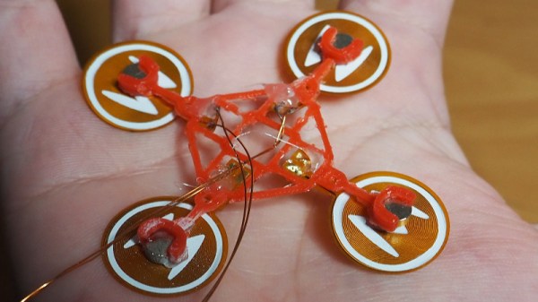
The aim is to build a walking robot that uses actuators made from flexible PCBs. The flexible PCB is printed with a coil, capable of generating a small magnetic field. This then interacts with a strong permanent magnet, causing the flexible PCB to move when energised.
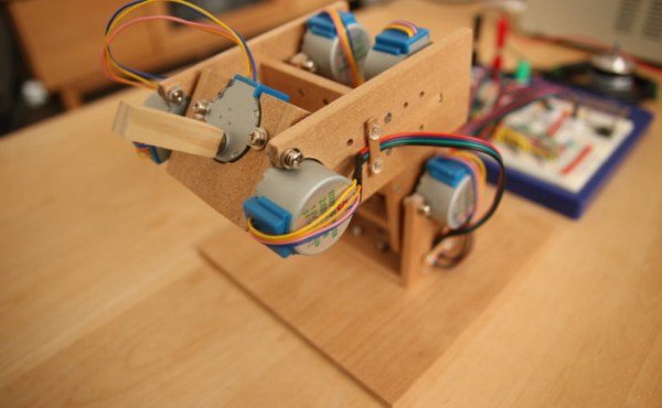
Initial attempts with four actuators mounted to a 3D printed frame were unsuccessful, but [Carl] has persevered. With a focus on weight saving, the MK II prototype has shown some promise, gently twitching its way across a desk in testing. Future steps will involve building an untethered version. This will replace the 3D printed chassis with a standard fibreglass PCB acting as both control board and the main chassis to minimise weight, similar to PCB quadcopter designs we’ve seen in the past.
We can’t wait to see the next revision, and if you’ve been working on your own walking robots, make sure you let us know.
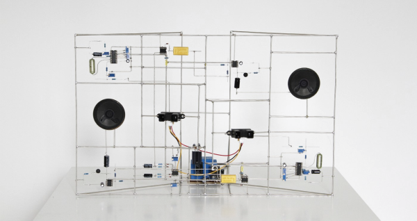
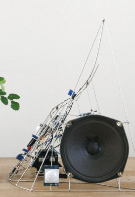 When it rains, it pours (wonderful electronic sculpture!). The last time we posted about freeform circuit sculptures there were a few eye-catching comments mentioning other fine examples of the craft. One such artist is [Eirik Brandal], who has a large
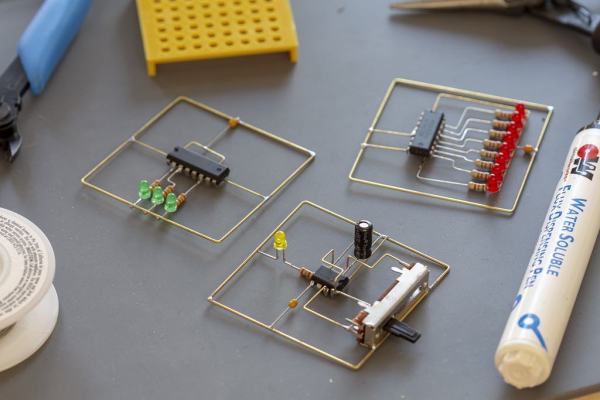
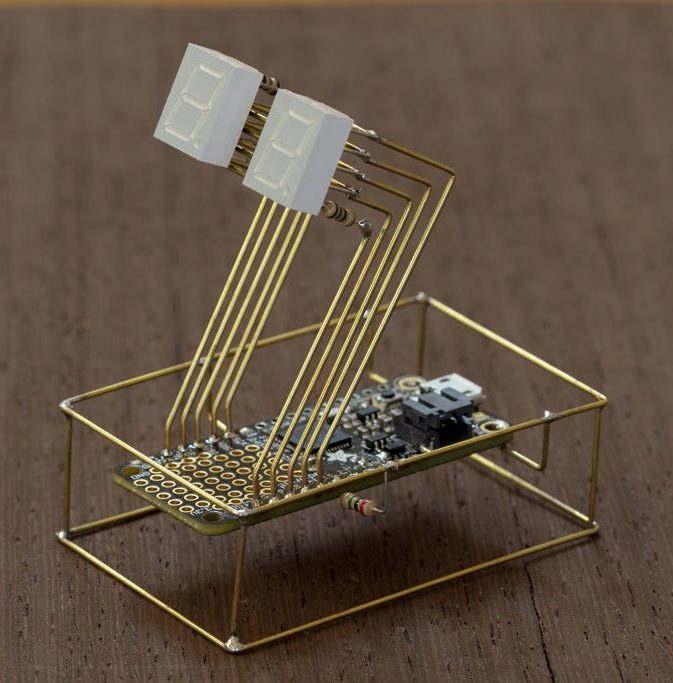
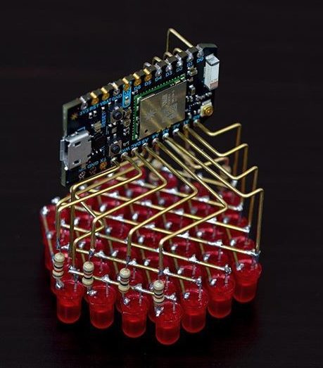
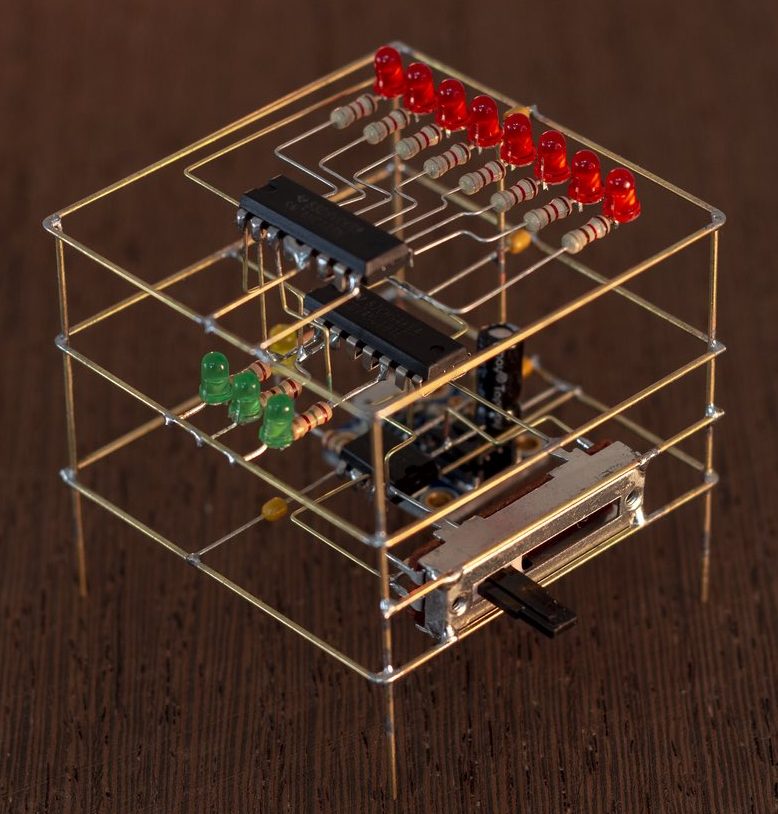
 tiny BGA components (ok, that one might be more cool than practical). Perhaps our favorite use is to create art, and [Mohit Bhoite] is an absolute genius of the form. He’s so prolific that it’s difficult to point to a particular one of his projects as an exemplar, though he has