Cheap nostalgia, that’s the name of the game. If you can somehow build and ship ‘cheap nostalgia’, you’re going to be raking in the bucks. For the ‘musicians’ in the crowd, the king of cheap nostalgia has something great. Behringer is cloning the Yamaha CS-80. and it was announced at this month’s Superbooth.
The Yamaha CS-80 is the synth in Blade Runner, and since Toto’s Africa is making a comeback on top-40 radio, it’s the instrument of our time. A Wonderful Christmas Time, it seems. Aaaannnyway, yes, there might be a huge and inexpensive version of one of the greatest synthesizers ever made real soon. The cheap 808s and 909s are making their way to stores soon, and the 101 needs a firmware update but you can buy it now. Cheap nostalgia. That’s how you do it.
The PiDP-11/70 is a project we’ve been neglecting for some time, which is an absolute shame. This is a miniature simulation of what is objectively the best-looking minicomputer of all time, the PDP-11/70. This version is smaller, though, and it runs on a Pi with the help of SimH. There are injection molded switches, everything is perfect, and now there are a whole bunch of instructional videos on how to get a PiDP-11/70 up and running. Check it out, you want this kit.
Considering you can put a phone screen in anything, and anyone can make a keyboard, it’s a wonder no one is making real, well-designed palmtop computers anymore. The Vaio P series of PCs would be great with WiFi, Bluetooth, and a slight upgrade in memory and storage. This was [NFM[‘s recent project. This palmtop gets an SSD. The object of modification is a decade-old Sony Vaio CPCP11 palmtop modified with a 256 GB SSD. The Vaio only supports PATA, and the SSD is mSATA, so this is really a project of many weird adapters that also have to be built on flex connectors.
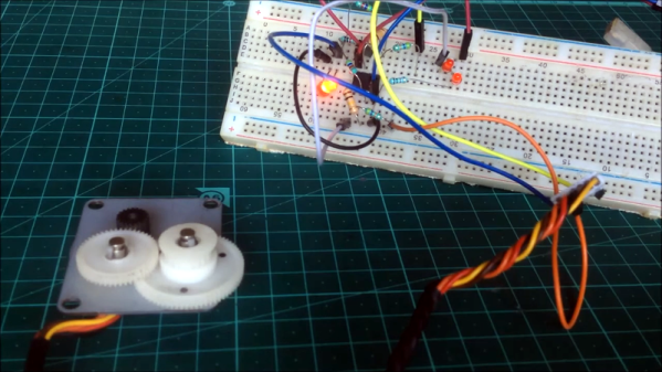
Here’s something for the brain trust in the Hackaday comments. First, take a look at this picture. It’s the inside of a rotary encoder. On the top, you have a Gray code (or what have you) that tracks the absolute position of a shaft. On the bottom, you have some sort of optical detection device with 13 photodiodes (or something) that keeps track of each track in the Gray code. This is then translated to some output, hopefully an I2C bus. What is this device, circled in red? I know what it is — it’s an optical decoder, but that phrase is utterly ungooglable, unmouserable, and undigikeyable. If you were me, what would you use to build your own custom absolute rotary encoder and you only needed the sensor? I technically only need 10 tracks/sensors/resolution of 1024, but really I only need a name.
Lol, someone should apply to Y Combinator and pitch yourself as a B Corp.