Humans have loved looking up at the night sky for time immemorial, and that hasn’t stopped today. [MattHh] has taken this love to the next level with the Pi-lomar Miniature Observatory.
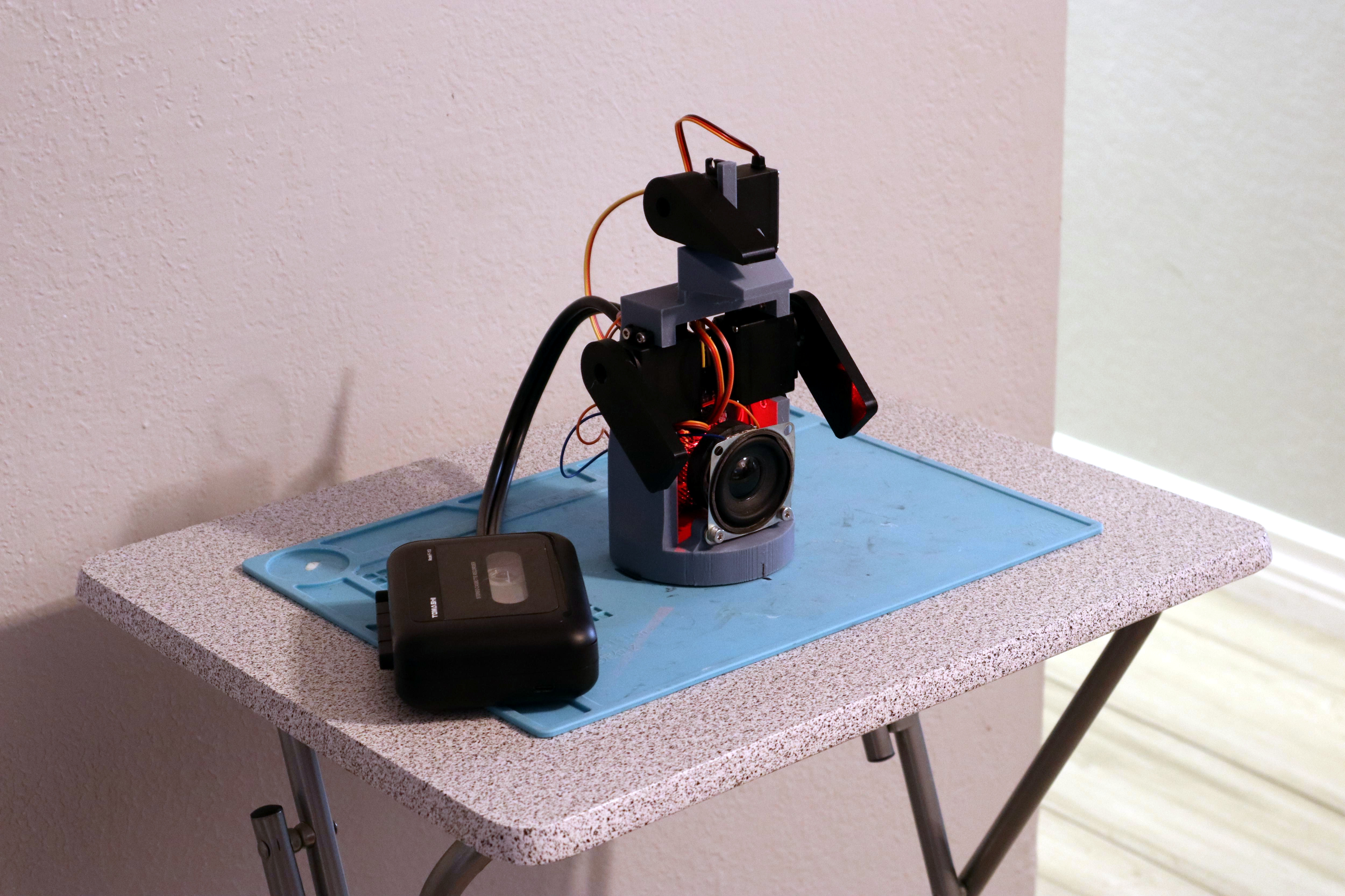
Built with a Raspberry Pi 4, a RPi Hi Quality camera, and a Pimoroni Tiny2040, this tiny observatory does a solid job of letting you observe the night sky from the comfort of your sofa (some assembly required). The current version of Pi-lomar uses a 16mm ‘telephoto’ lens and the built-in camera libraries from Raspbian Buster. This gives a field of view of approximately 21 degrees of the sky.
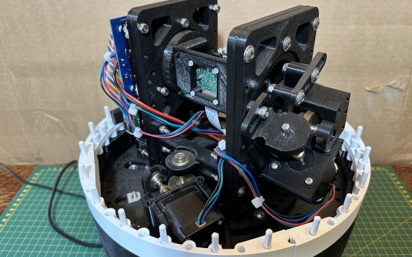
While small for an observatory, there are still 4 spools of 3D printing filament in the five different assemblies: the Foundation, the Platform, the Tower, the Gearboxes and the Dome. Two NEMA 17 motors are directed by the Tiny2040 to keep the motion smoother than if the RPi 4 was running them directly. The observatory isn’t waterproof, so if you make your own, don’t leave it out in the rain.
If you’re curious how we might combat the growing spectre of light pollution to better our nighttime observations, check out how blinking can help. And if you want to build a (much) larger telescope, how about using the Sun as a gravitational lens?
Continue reading “Pi-lomar Puts An Observatory In Your Hands”