When designing a mains power supply for a small load DC circuit, there are plenty of considerations. Small size, efficiency, and cost of materials all spring to mind. Potential lethality seems like it would be a bad thing to design in, but that didn’t stop [Great Scott!] from exploring capacitive drop power supplies. You know, for science.
The backstory here is that [Great Scott!] is working on a super-secret ATtiny project that needs to be powered off mains. Switching power supplies are practically de rigueur for such applications, but compared to the intended microcontroller circuit they are actually quite large, and they’ve just been so done before. So in order to learn a thing or two, [Scott!] designed a capacitive dropper supply, where the reactance of the cap acts like a dropping resistor to limit the current. His first try was just a capacitor in series with an LED; this didn’t end well for the LED.
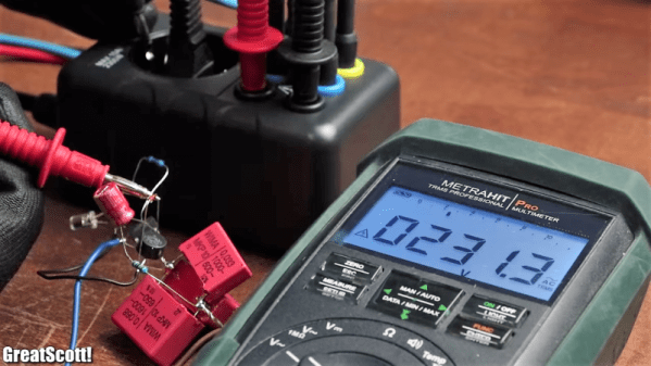
To understand why, he reverse-engineered a few low-current mains devices and found that practical capacitive droppers need a few more components, chiefly a series resistance to prevent inrush current from getting out of hand, but also a bridge rectifier and a zener to clamp things down. Wiring up all that resulted in a working capacitive dropper supply, but a the cost of as much real estate as a small switcher, and with the extra bonus of being potentially lethal if the power supply is plugged in the wrong way. Side note: we thought German line cords were polarized to prevent this, but apparently not? (Ed Note: Nope!)
As always, even when [Great Scott!]’s projects don’t exactly work out, like a suboptimal 3D-printed BLDC or why not to bother building your own DC-AC inverter, we enjoy the learning that results.
Continue reading “Mains Power Supply For ATtiny Project Is Probably A Bad Idea”