When first starting an electronics project, it’s not uncommon to dive right in to getting the core parts of the project working. Breadboarding the project usually involves working with a benchtop power supply of some sort, but when it comes to finalizing the project the actual power supply is often glossed over. It’s not a glamorous part of a project or the part most of us want to be working with, but it’s critical to making sure projects don’t turn up with mysterious issues in the future. We can look to some others’ work to simplify this part of our projects, though, like this power supply from [hesam.moshiri].
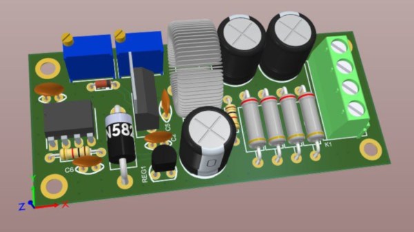
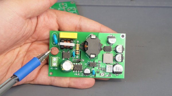
The power supply is designed around a switch-mode topology known as a flyback converter. Flyback converters work by storing electrical energy in the magnetic field of a transformer when it is switched on, and then delivering that energy to the circuit when it is switched off. By manipulating the switching frequency and turns ratios of the transformer, the circuit can have an arbitrary output voltage. In this case, it is designed to take 220V AC and convert it to 8V DC. It uses a simplified controller chip to decrease complexity and parts count, maintains galvanic isolation for safety, and is built to be as stable as possible within its 24W power limitation to eliminate any potential issues downstream.
For anyone trying to track down electrical gremlins in a project, it’s not a bad idea to take a long look at the power supply first. Any noise or unwanted behavior here is likely to cause effects especially in projects involving sensors, ADC or DAC, or other low-voltage or sensitive components. The schematic and bill of materials are available for this one as well, so anyone’s next project could use this and even make slight adjustments to change the output voltage if needed. And, if this is your first introduction to switched-mode power supplies, check out this in-depth look at the similar buck converter circuit to better understand what’s going on behind the scenes on these devices.
Continue reading “AC-DC Converter Is Reliable, Safe, And Efficient”