The Electrical Outlet And How It Got That Way

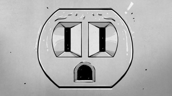
Right now, if you happen to be in Noth America, chances are pretty good that there’s at least one little face staring at you. Look around and you’ll spy it, probably about 15 inches up from the floor on a nearby wall. It’s the ubiquitous wall outlet, with three holes arranged in a way that can’t help but stimulate the facial recognition firmware of our mammalian brain.

No matter where you go you’ll find those outlets and similar ones, all engineered for specific tasks. But why do they look the way they do? And what’s going on electrically and mechanically behind that familiar plastic face? It’s a topic we’ve touched on before with Jenny List’s take on international mains standards. Now it’s time to take a look inside the common North American wall socket, and how it got that way.

Continue reading “The Electrical Outlet And How It Got That Way”

Ask Hackaday: Whatever Happened To Wire Wrapping?

Back in the 70s when I started getting interested in electronics, tons of magazines catered to the hobbyist market. Popular Electronics was my favorite, and I think I remember the advertisements more than anything, probably because they outnumbered articles by a large margin. Looking back, it seemed like a lot of ad space was sold to companies hawking the tools and materials needed for wire wrapping, which was very popular for prototyping in the days before solderless breadboards were readily available. I remember beauty shots of neat rows of small, gold posts, with stripped wires wrapped evenly around them.

To the budding hobbyist, wire wrapping looked like the skill to have. With a huge selection of posts, terminals, and sockets for ICs and discrete components, as well as a wide range of manual and powered wrapping tools, it seemed like you could build anything with wire wrapping. But fast forward just a decade or so, and wire wrapping seemed to drop out of favor. And today — well, does anyone even wire wrap anymore?

Continue reading “Ask Hackaday: Whatever Happened To Wire Wrapping?”

Why Won’t This Darn Thing Charge?

What is more fun than plugging in your phone and coming back to find your battery on empty? Stepping on a LEGO block with bare feet or arriving hungry at a restaurant after closing probably qualify. [Alex Sidorenko] won’t clean your floors or order you a pizza, but he can help you understand why cheap chargers won’t always power expensive devices. He also shows how to build an adapter to make them work despite themselves.

The cheapest smart device chargers take electricity from your home or car and convert it to five volts of direct current. That voltage sits on the power rails of a USB socket until you plug in a cable. If you’re fortunate, you might get a measly fuse.

Smart device manufacturers don’t make money when you buy an off-brand charger, and they can’t speak to the current protection of them, so they started to add features on their own chargers to protect their components and profit margins. In the case of dedicated chargers, a simple resistor across the data lines tells your phone it is acceptable power. Other devices are more finicky, but [Alex Sidorenko] shows how they work and provides Eagle files to build whatever flavor you want. Just be positive that your power supply is worthy of the reliability these boards promise to the device.

Now you know why connecting a homemade benchtop power supply to a USB cable seems good on paper but doesn’t always get the job done. Always be safe when you make your own power supplies.

Building A WiFi Enabled Nixie Counter

wifi-nixie-counter

[Kevin Ballard] built this Nixie counter on the company dime. Tubes like this are getting more and more difficult to find since they’re no longer being manufactured. But when the Bossman hands you a corporate credit card those kinds of concerns take a back seat to your parts-shopping impulses. Start to finished this WiFi enabled counter took six weeks to build.

Connecting the board to the internet was very easy thanks to the Electric Imp that drives it. The difficult part comes in building a driver board and sockets for the tubes. We don’t see a lot of detail on how he’s generating the high voltage. But you can get a good feel for the tube connectors from the picture. He’s using an adapter PCB from Kosbo which breaks the tube pins out to two rows of 0.1″ pitch pin headers. The acrylic base has a port for each made of pin sockets spaced by a thick chunk of acrylic. Wiring harnesses wrap around the back side of the base to mate with the driver hardware. It’s programmed to count some type of company metric (it was funded by the corporation after all). They must be fairly successful because those numbers are flying by in the demo video.

Continue reading “Building A WiFi Enabled Nixie Counter”

Machining Cartridge Connectors From PCI Sockets

[Ed] needed a bunch of edge connectors for video game cartridges. He was unable to source parts for Neo Geo Pocket games and ended up building his own from PCI sockets. But it sounds like this technique would work with other console cartridges as well.

From the picture you can see that this is a bit more involved than just slapping a cartridge into a socket. Because there are multiple steps, and many connectors were needed, [Ed’s] dad lent a hand and built a few jigs to help with the cutting. The first step was to cut off the key and the narrow end of the socket. These NGP cartridges are one-sided, so the socket was cut in half using a board with a dado cut in it as a jig. From there the plastic bits can be cleaned up before pulling out two center pins and cutting a groove to receive the cartridge key. There are also two shoulder cuts that need to be made after trimming the piece to length. The video after the break will walk you through this whole process.

These PCI sockets are versatile. One of our other favorite hacks used them to make SOIC programming clips.

Continue reading “Machining Cartridge Connectors From PCI Sockets”

Build Your Own SOIC Progamming Clip

[Pyra] was looking for a way to reprogram some ATtiny13 microcontrollers in a SOIC package. He’s re-engineering some consumer electronics so adding an ISP header to the design isn’t an option. He had been soldering wires to the legs of every chip but this is quite tedious. What he needs is an adapter that can make physical contact with the legs just long enough to program new firmware. After looking around he discovered that a PCI socket can be used as a progamming clip (translated). It shares the same pitch as a standard SOIC package but is not wide enough for the chip. He cut out 4 rows of the socket and the section of motherboard it was soldered to. Then he made a cut down the middle of the plastic and bent the two sections apart. The image above illustrates this, but not shown are the eight wires that he later added to connect to the device.

We wonder if this can be adapted to program SOIC parts without removing them from a circuit board. That would be a handy tool for finishing up the LED lightbulb hack.

AVR Dragon Wiring Alternative

dragon_jumper_board

We love our AVR Dragon programmer. It is a small board with a lot of functionality: in-circuit serial programming, JTAG, debug wire, and high voltage serial programming. Unfortunately, out of the box it is not quite ready for action. The Dragon ships with an unpopulated prototyping area and missing a pin header for the HVSP. For most people this means soldering on pin headers and a ZIF socket then jumpering between the various programming headers and the header for the socket. Tired of working with jumper wires, [Jussi] designed a small PCB to make the connections (original link in Finnish). Continue reading “AVR Dragon Wiring Alternative”