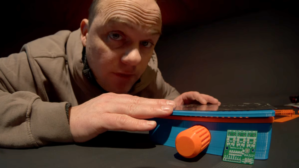
Syringes are pretty ergonomic, but when manually dispensing flux and solder paste it doesn’t take long before one wants a better way. [Elektroarzt]’s flux and solder paste dispenser design uses 3D-printed parts and minimal hardware (mostly M3x20 screws, and an optional spring) to improve handling and control.
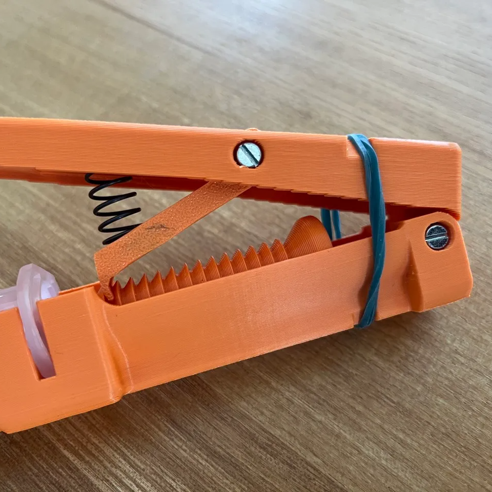
How does it work? The ratcheting lever mechanism is similar to that of a hot glue gun, where an arm slips into notches in a rod when pressed down, driving it forward and never backward. In the process, a larger lever movement is translated into a shorter plunger travel, enhancing control.
The types of syringes this tool is meant to be used with have a plunger tip or piston (the rubber stopper-looking part, in contact with the liquid) inside the loaded syringe, but no plunger shaft attached to it. This is common with syringes meant to be loaded into tools or machines, and [Elektroarzt]’s tool can be used with any such syringe in a 10 cc size.
It’s an attractive design, and we like the way syringes top-load as well as the way the tool is made to lay flat on a tabletop, with the lever pointed up.
Want truly fine-grained control over your extrusions? Then check out this dispenser which really lets one dial in small amounts. You can also go motorized, and let a small PCB and stepper motor do the work.