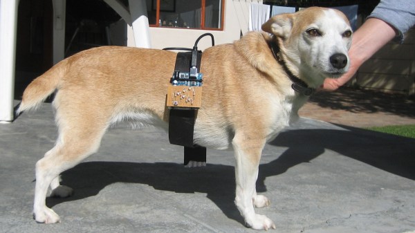
[Johan Beyers] built an elegantly simple Dog Speedometer project that uses a POV display to display a running dog’s speed without the benefit of an accelerometer. Using an Arduino (looks like it might be a D-love) and a line of 5 LEDs, [Johan] built a dirt-simple POV — 39 lines of code — that times out the flashes so that an immobile viewer sees the dog’s speed. How do you know your pup’s loping speed? That’s the beauty of this project.
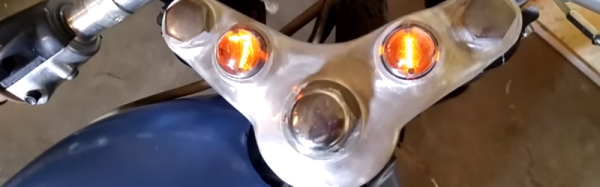
Instead of putting all of the LEDs in a line, they are arranged in a V-shape. Because of this spatial offset, the patterns flashed out only “look right” at the right speed. Each number is flashed at a different speed, so you just look for the least distorted numeral.
[Johan]’s code does only what it needs to get the job done. The character data are stored in arrays that are played back directly to the pins of PORTD — avoiding most of the usual Arduino-style complexity with pin definitions and other foolery.
POV displays can be leveraged to add pizzazz to any project — this CD-ROM POV clock and this wind-powered POV weather station come to mind.
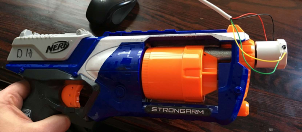
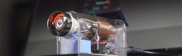
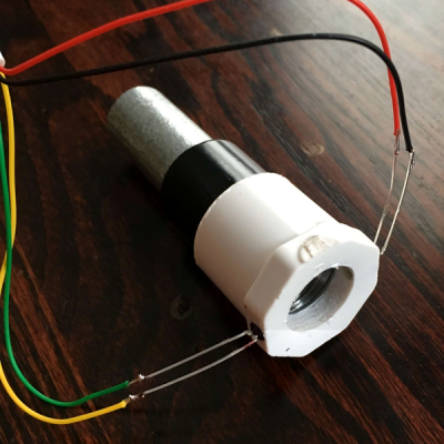 First, he prototyped a single beam-break detector (shown above) and then expanded his build to two in order to get velocity info. A Propeller microcontroller took care of measuring the timing. Then came the gratuitous statistics. He took six different darts and shot them each 21 times, recording the timings. Dart #3 was the winner, but they all had similar average speeds. You’re not going to win the office NERF war by cherry-picking darts.